Scooter Battery Teardown Part 2: Electric Boogaloo

It was past time to get back at the battery module, to figure out how I'm going to harvest all the cells before I even consider how to put them together into a new module. Together with my battery-massacring compatriot, we resolved to finish the job. When we last left our patient, it looked like this:
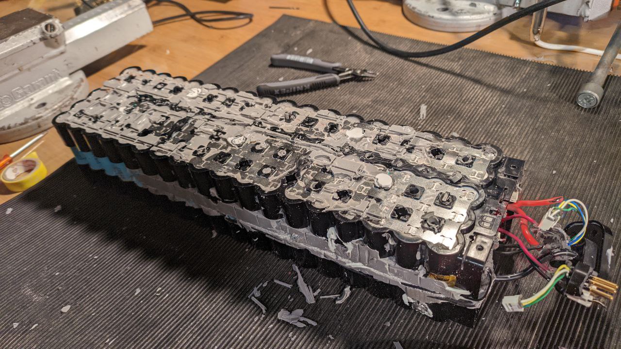
A battery pack

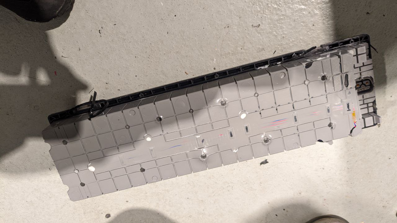
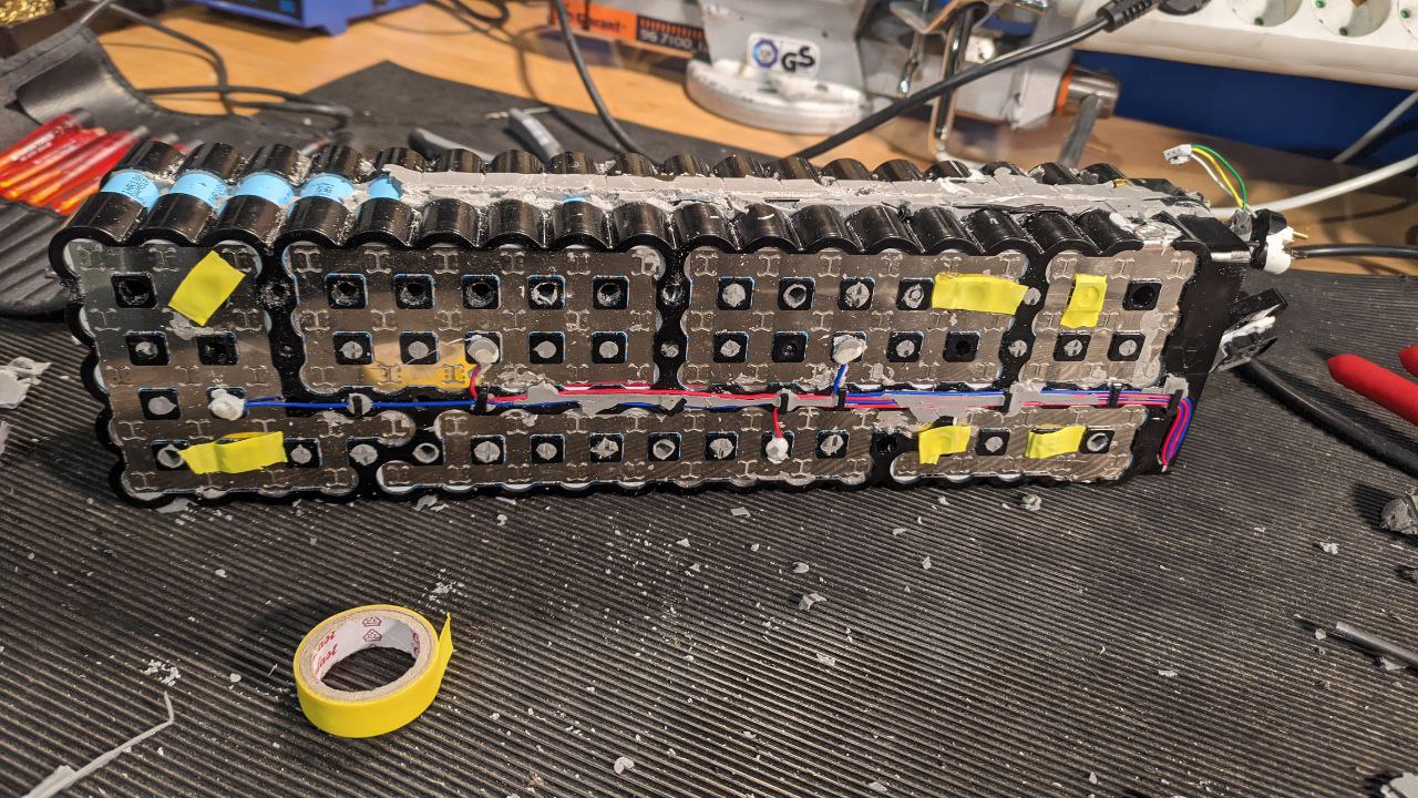
With the assistance of a drill press and a 5.5mm bit, we reamed out the rest of the spaces between cells. It turns out, the two parts of the shell are screwed together!
A battery pack with yellow electrical tape over some holes

It seems every second hole is an opportunity for a screw (some marked with yellow, above). However, even after reaming, the shells still wouldn't come apart. We took a detour and popped out the BMS Board...
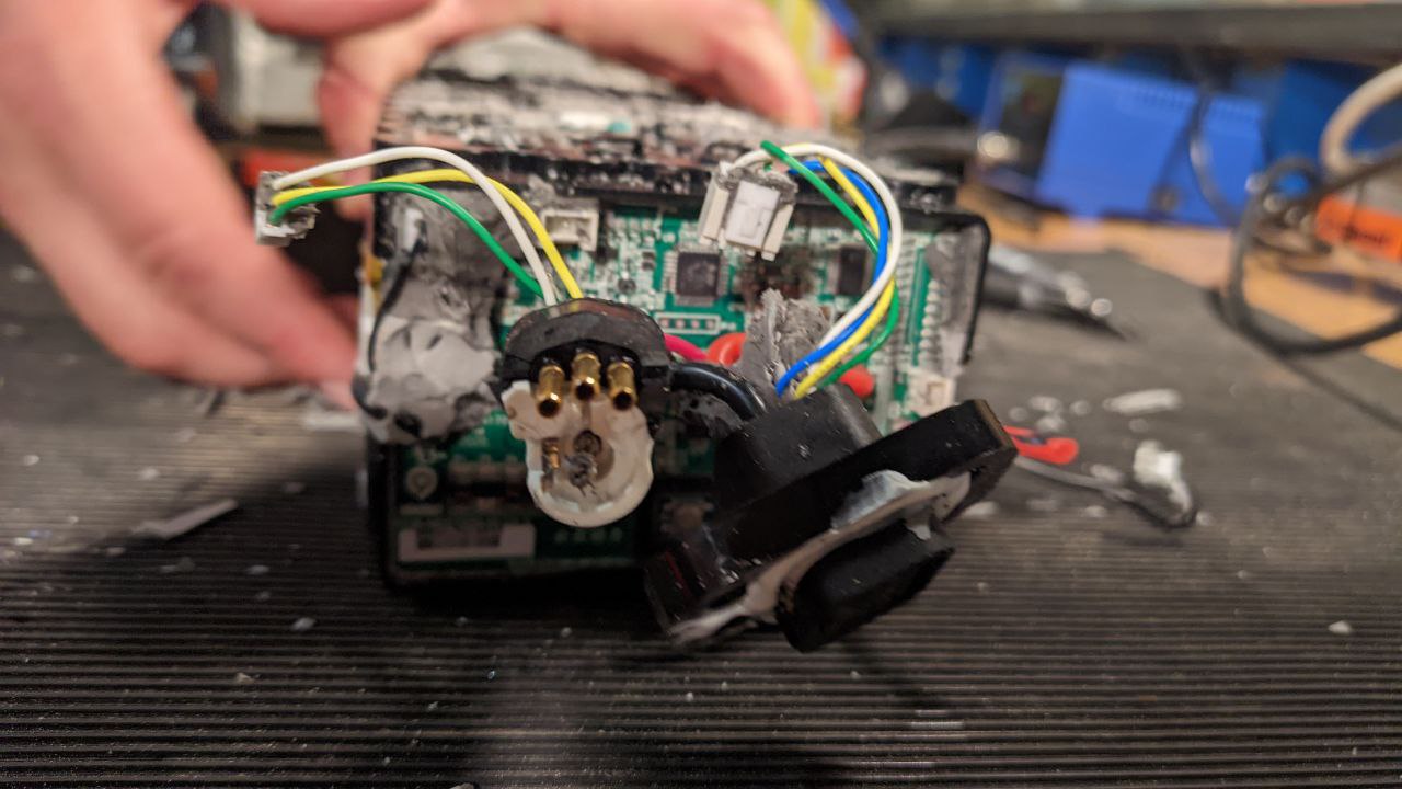
Wires coming out of a BMS

Which was hiding under a mass of filler materials. Here is the dead BMS, front and back, freed from its silicone prison.
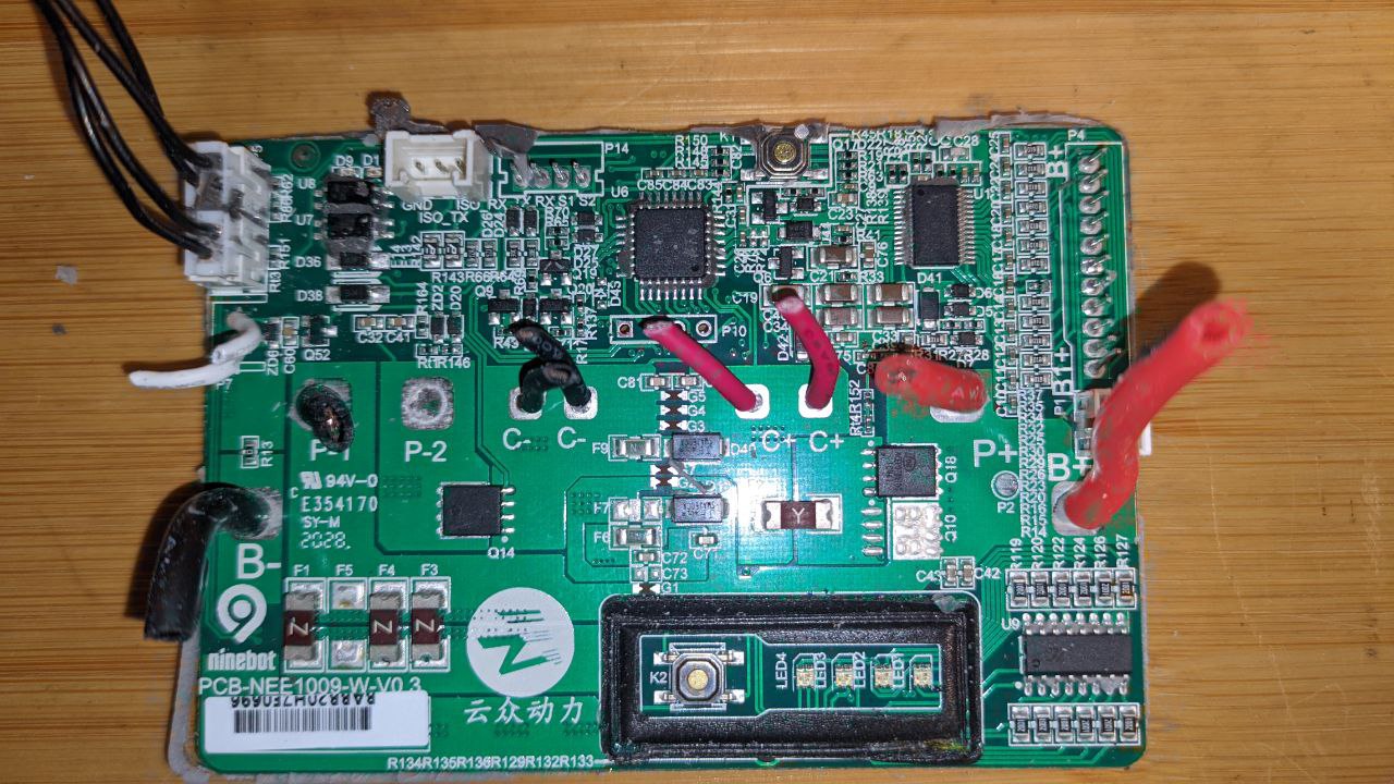
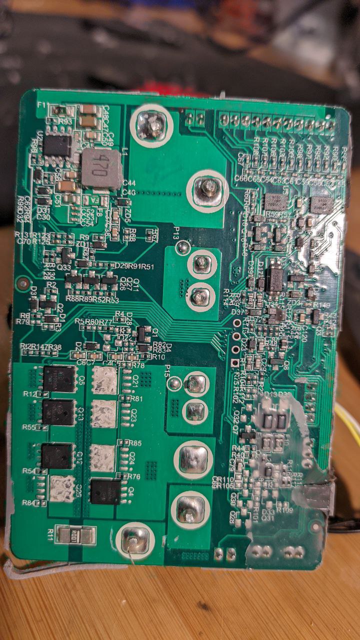
Front of the BMS Back of the BMS

If I cared at all about the BMS part, I'd look at the STM32G0 a bit closer... but I don't :) There was a very interesting thermal fuse included:
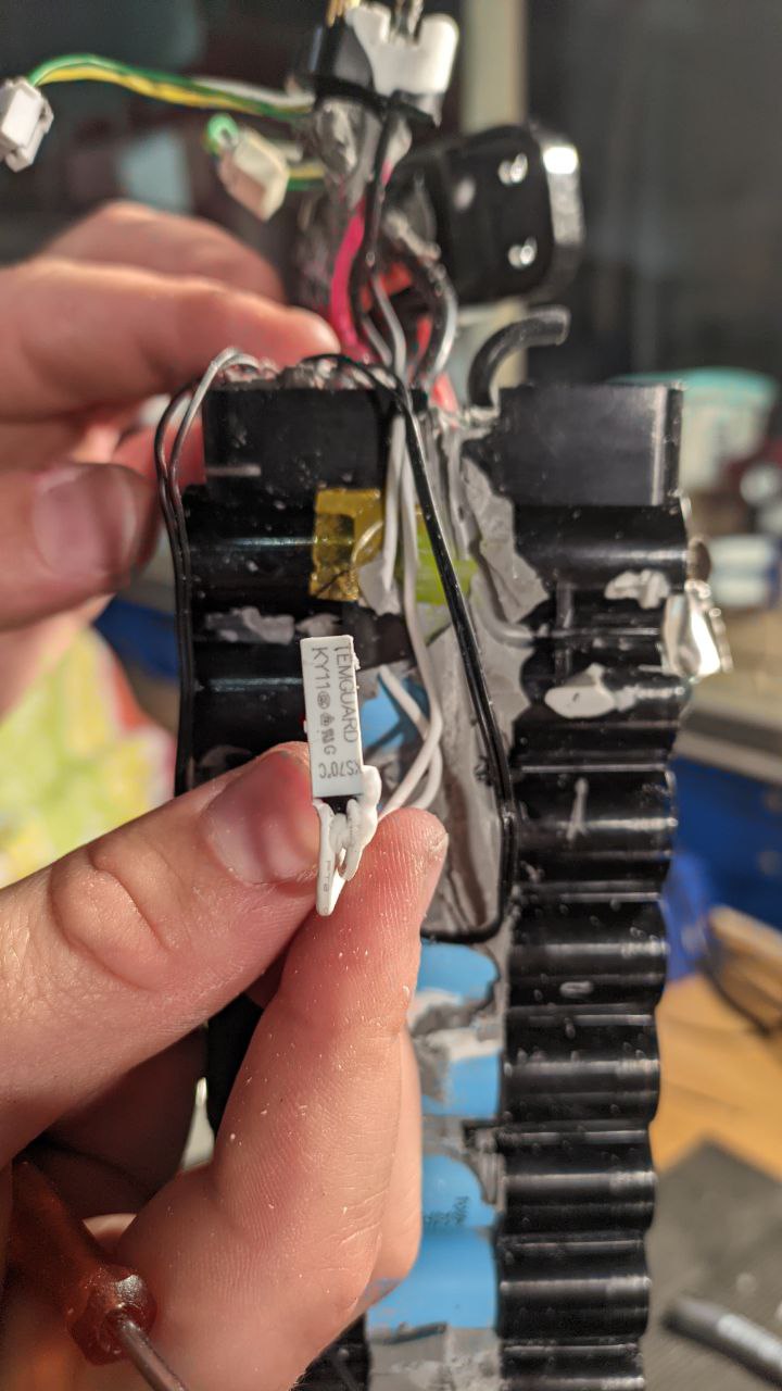
The thermal fuse

It was then that the scope of the task made itself readily apparent:
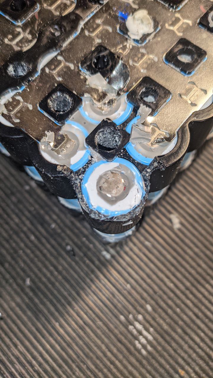
The secret is revealed

The battery pack is designed in such a way that it goes together quite easily, and is extremly rigid and robust against vibrations and other mechanical stress. The nickel collector plates are likely welded after the frames are on, as the nickel plates form part of the retention mechanism for the cells (together with a little bit of plastic which overlaps each cell). This will be a nightmare to disassemble with only hand tools.
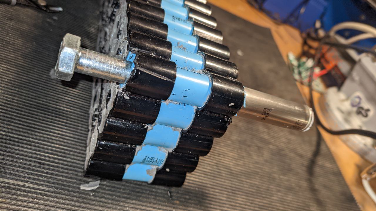
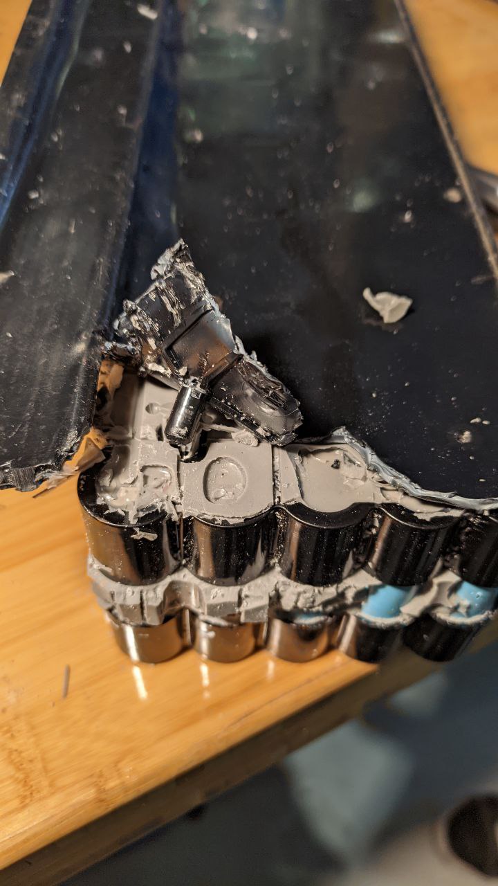
A victim cell appears

Nevertheless, we would not be denied our prize. With some diagonal cutters and some very careful surgery, we were able to cut the supporting material away from one of the cells in the corner and then very carefully tap it out with a bolt.
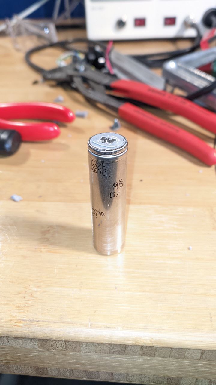
The prize

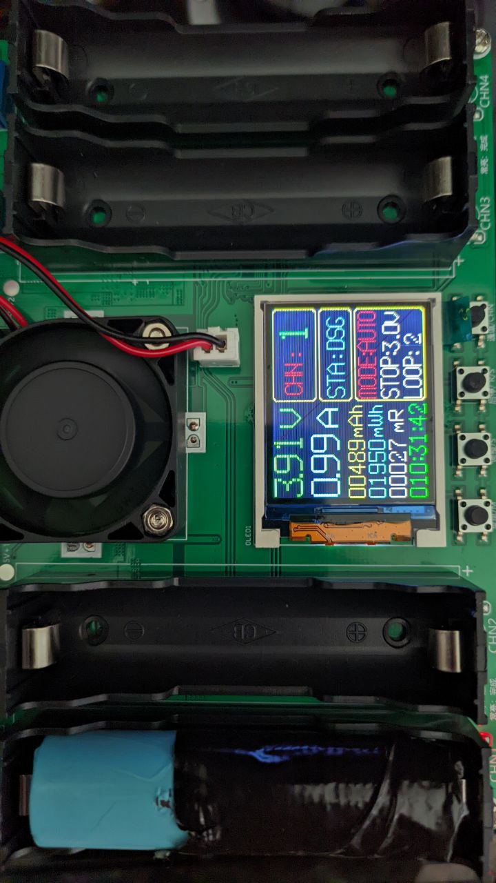
I took the cell home and threw it in the battery cell tester for a few charge/discharge cycles:
Tester

27 milliOhm is within the 35 max specified for the battery, and once the testing cycle is complete we'll see how much capacity is left--I am expecting quite a bit.

As to how to deal with the other cells and battery packs... well. They have to go a bit more smoothly. In the meantime I will get some replacement insulation sleeves and rings to ensure everything is in tip-top shape for the eventual pack construction.
Scooter Battery Teardown Part 1

Scooter Battery Teardown Part 1

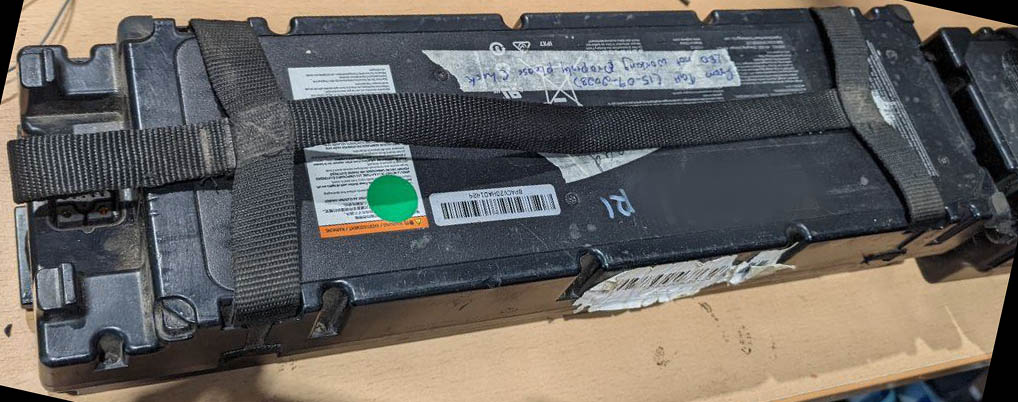
I took some time today to start trying to understand what exactly it was that I'd gotten my hands on: It was time to figure out how I was going to harvest the cells from the battery packs I received, and if they would even be worth anything. The battery packs I got are NEE1009-W, and since I have 77 of them, I wanted also to start to plan for how to tear them all down as efficiently as possible. I enlisted the help of a friend, and we got out my pack of chisels and went at it.

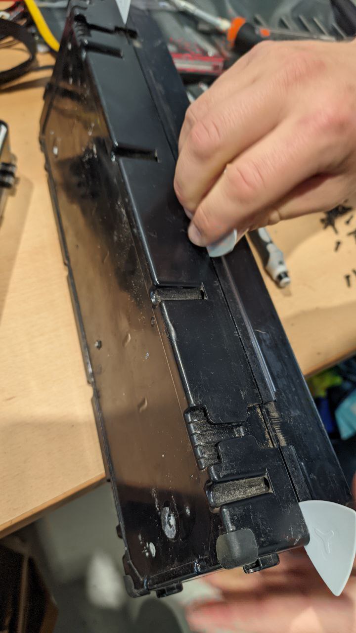
Splitting the battery case with guitar picks – simple, effective, and surprisingly gentle on the plastic.

Splitting the battery case with guitar picks – simple, effective, and surprisingly gentle on the plastic.

With the top removed, a first look at the cells and their arrangement, each one neatly encased and connected. With the top removed, a first look at the cells and their arrangement, each one neatly encased and connected.
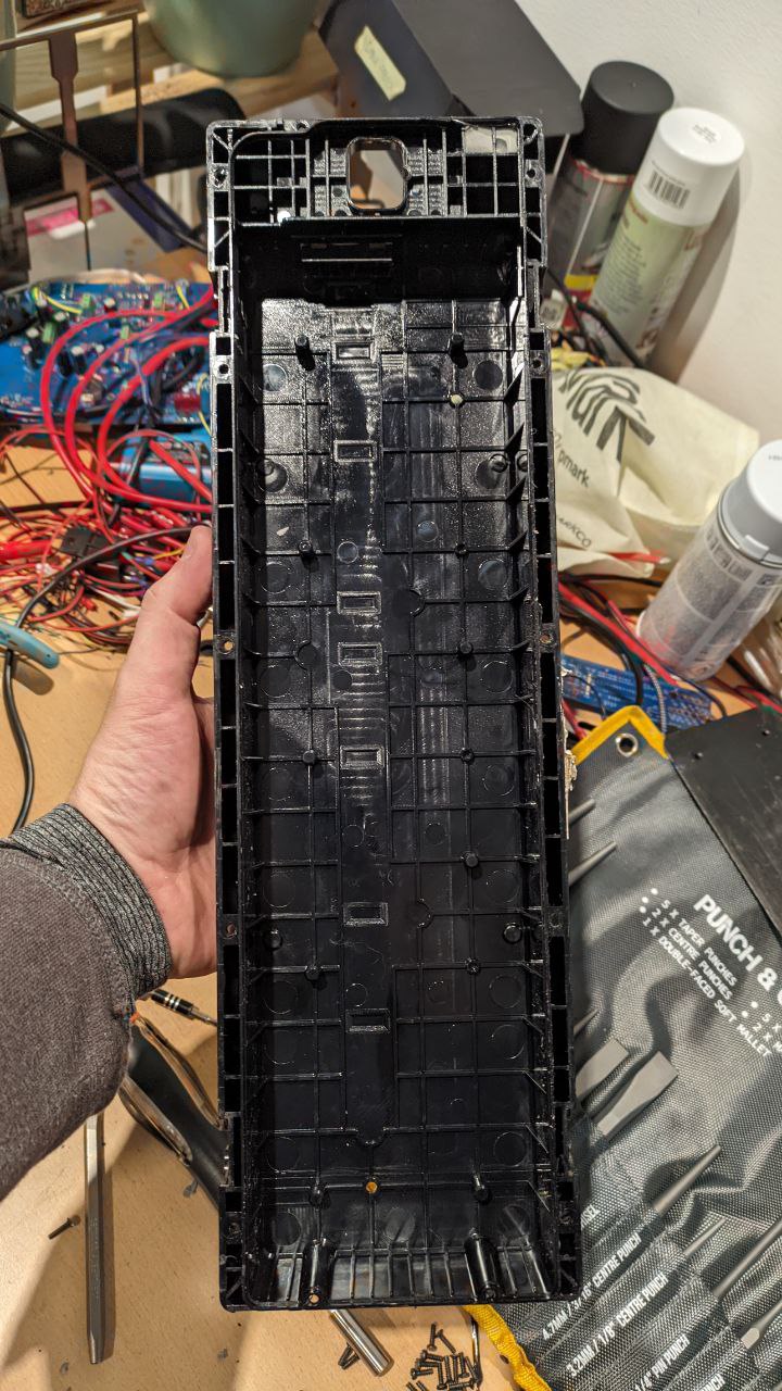
The lone top case. The lone top case.
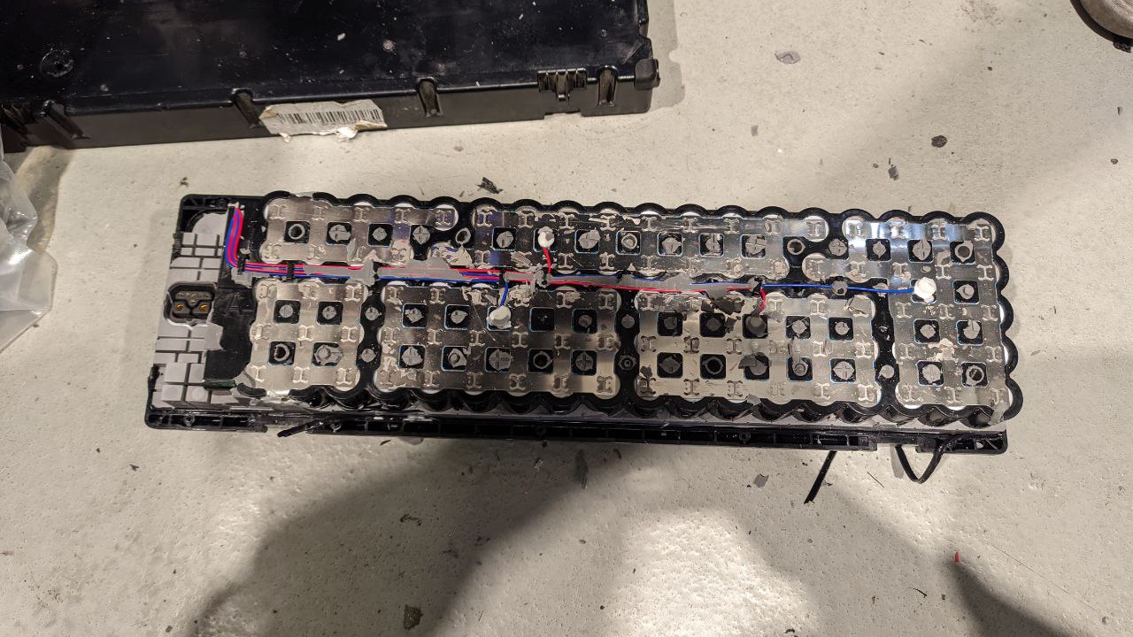
Removing the silicone reveals a detailed network of cells. Removing the silicone reveals the electrical architecture of the battery pack.
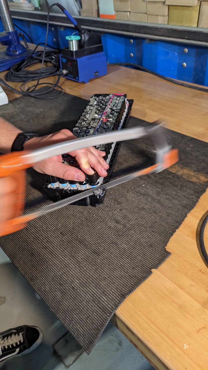
Hacksaw Time Sometimes you just need a hacksaw...

Peeling back the lower plastic Peeling back the lower plastic
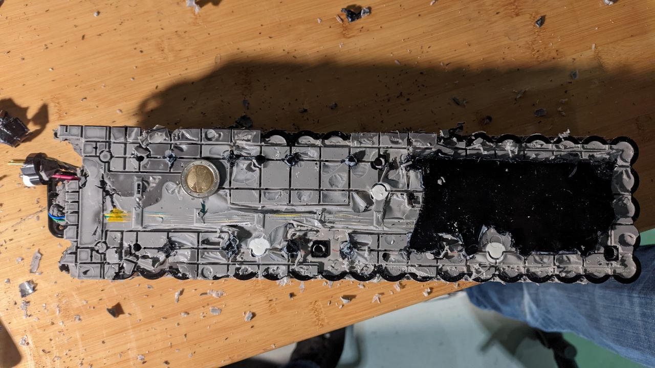
Finally, the battery pack stands bare Finally, the battery pack stands bare. We ran out of time, but did manage to verify that all the cells are okay--the groups measured out to 3.7v and the whole pack was still at ~36V
We came up with some ideas for how to improve the process (pressured air, drill press to grind out some of the enclosure knobs, etc.) and will see about getting the individual cells out in the upcoming days and coming up with a polished process.

Battery Volume Exploration

Battery Volume Exploration

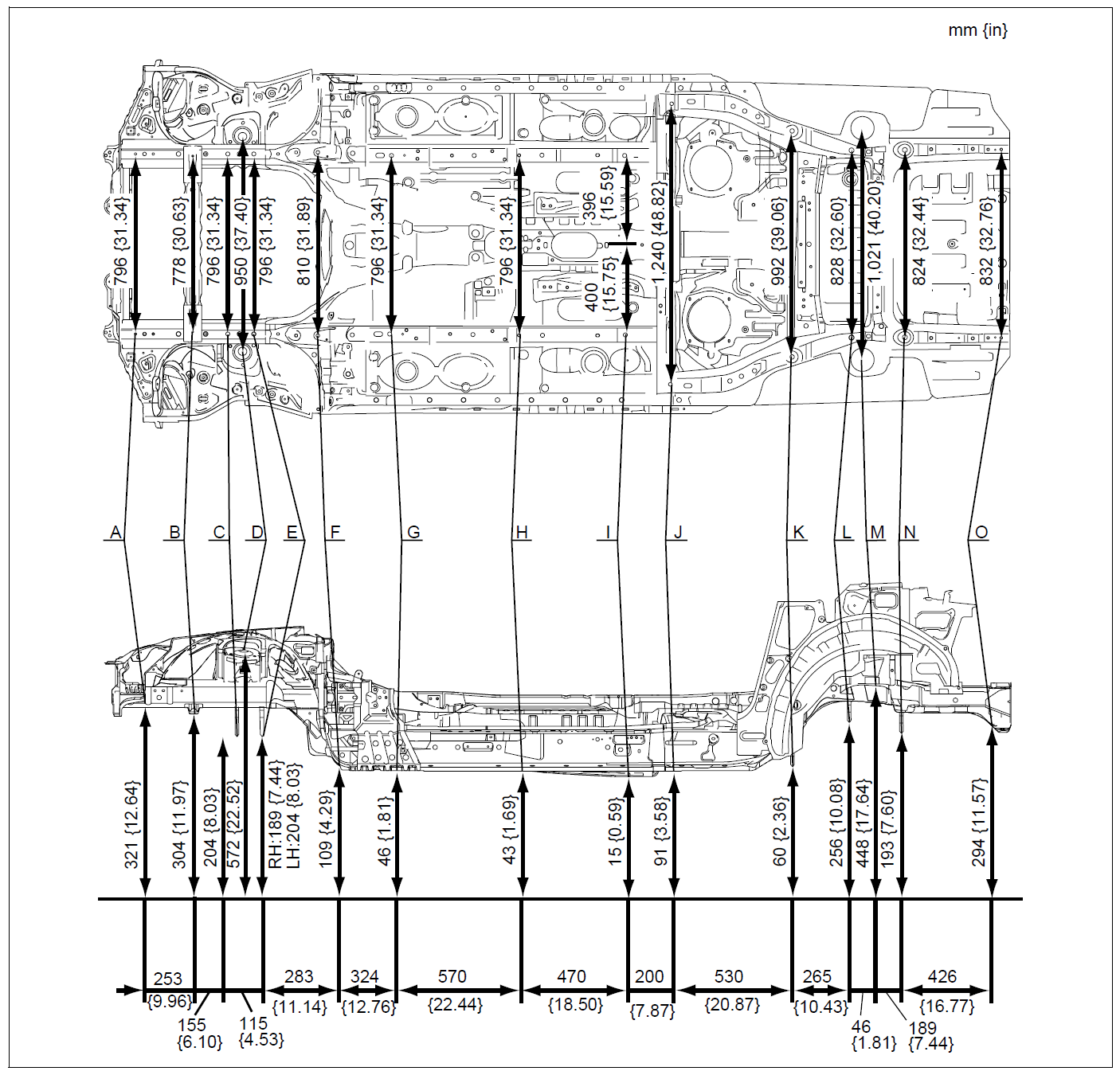
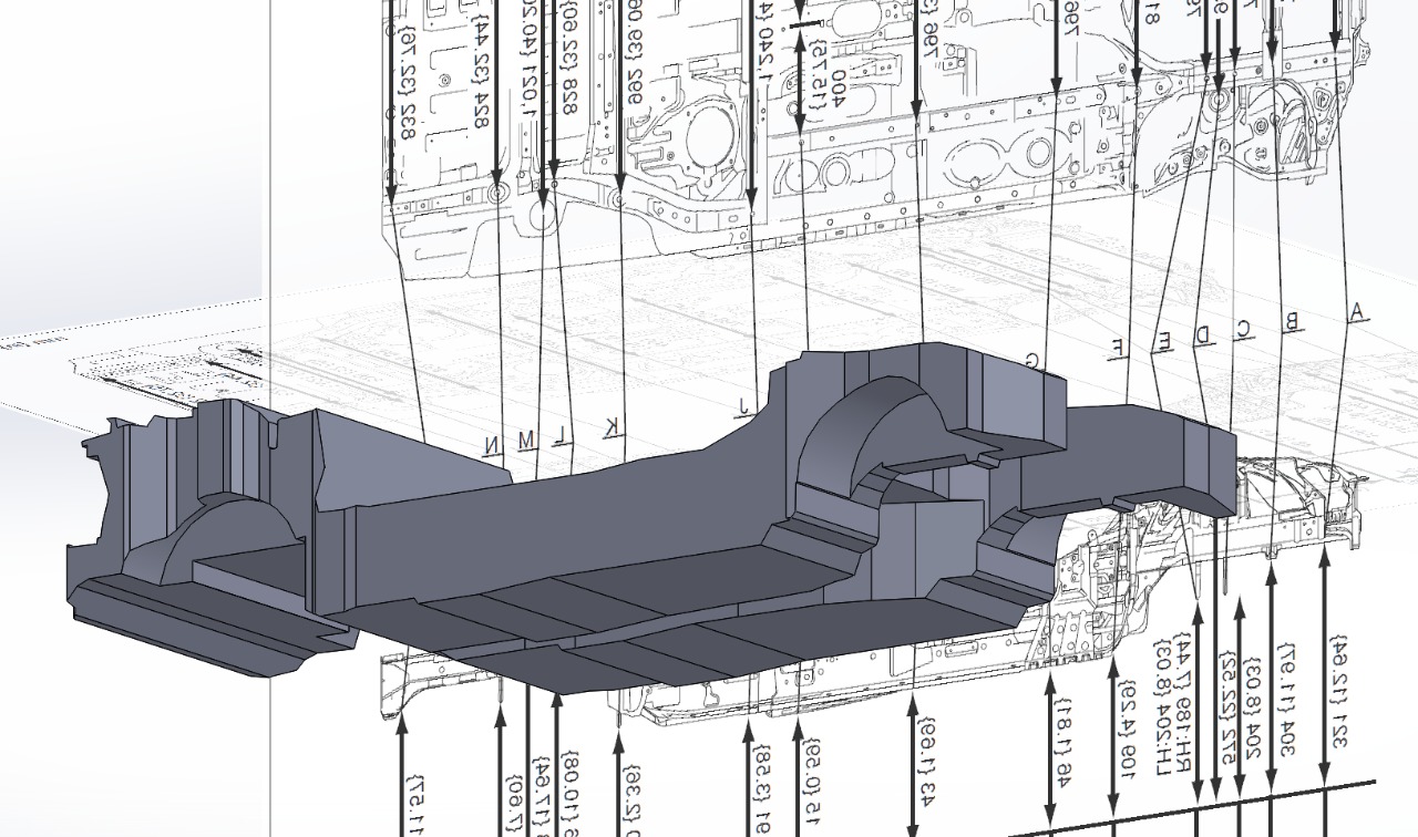
I spent some time last night bothering friends of mine while I was drafting a rough version of the chassis to understand how much volume will be available for the battery module (which is next to be designed). The body shop manual was very helpful, but not 100% complete, so some of the measurements were useful after all.

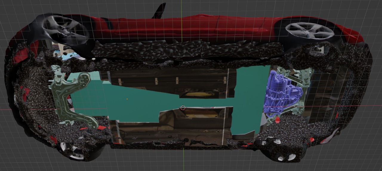
chassis mid-draft

Conservatively, it looks like between the part of the fuel tank which isn't occupied by the motor, the transmission tunnel, and the area formerly occupied by the long block, there's around 380L of space for the battery pack, which has to include the battery cells themselves as well as any structure, wiring, bus bars, cooling, etc.

roughed-out chassis with battery volume highlighted

Using the existing NINEBOT scooter batteries as a rough reference for weight and volume (for a combined pack with overheads, not the individual cells), it looks like each kWh is about 4.4L, and will weigh about 7.3kg.

As the current plan is to build a 53.5kWh battery pack, that would mean the expected volume utilization is only 240L. Having "so much" extra space available is really good, as I expect that to shrink due to additional packaging and cooling overhead, and it will let me ensure the center of mass and weight distribution changes a little as possible.

Speaking of weight, I ran through the list of things which are being removed vs the things which are being added:

  • renesis engine: 297pounds
  • transmission: 80 pounds
  • rear diff: 75 pounds
  • exhaust: 40 pounds
  • full gas tank: 100 pounds

sum old bits: 592 pounds, 270kg

  • battery pack - 53.5kWh * 7.3kg = 390kg
  • motor: 90kg
  • AC/DC, DC/DC, and PDU: 15kg

sum new bits: ~500kg

so it looks like the car will gain about 230kg, which according to this spec sheet is within the cargo capacity of 425kg.

Roughing out the motor location

Roughing out the motor location

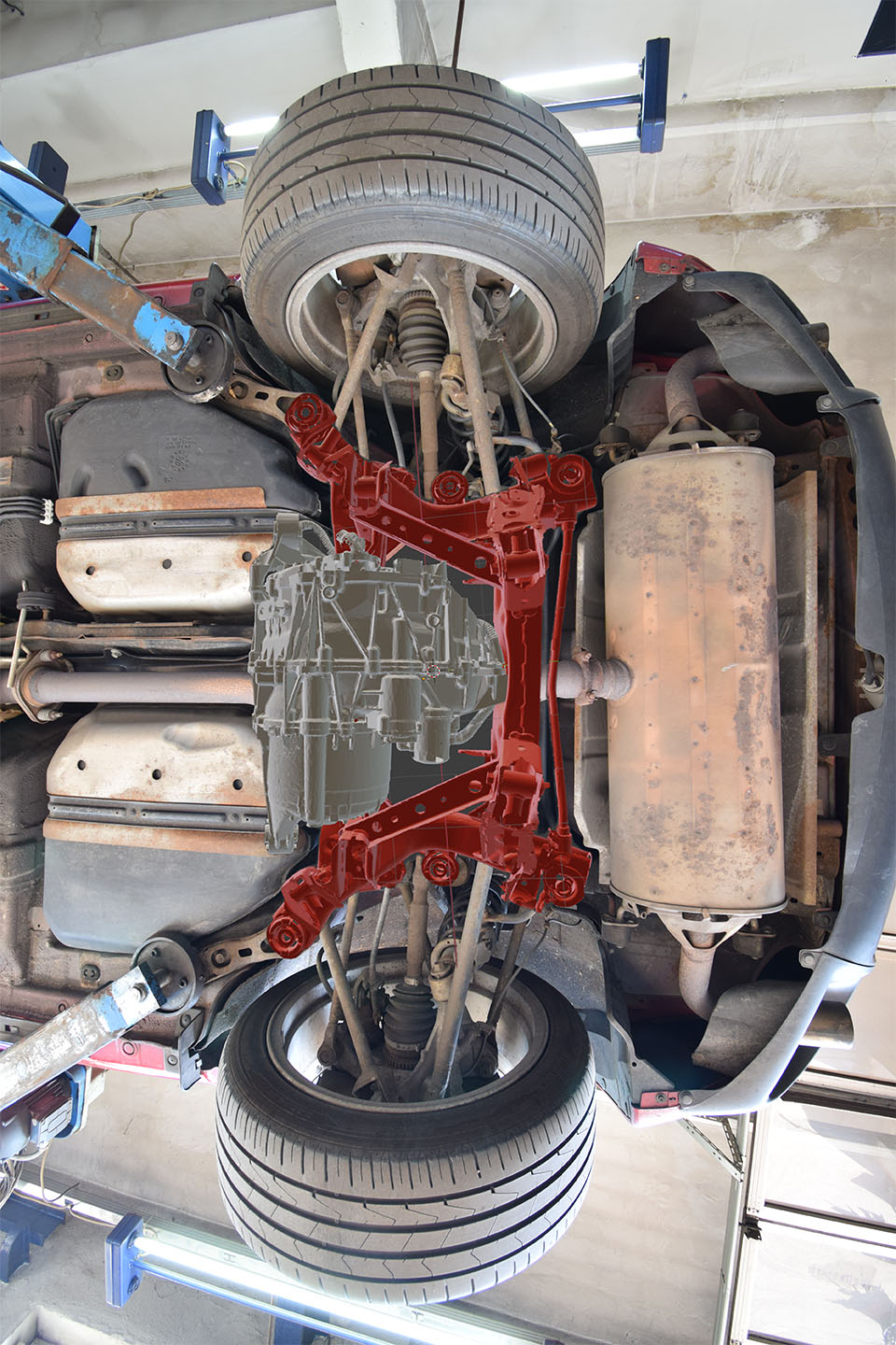
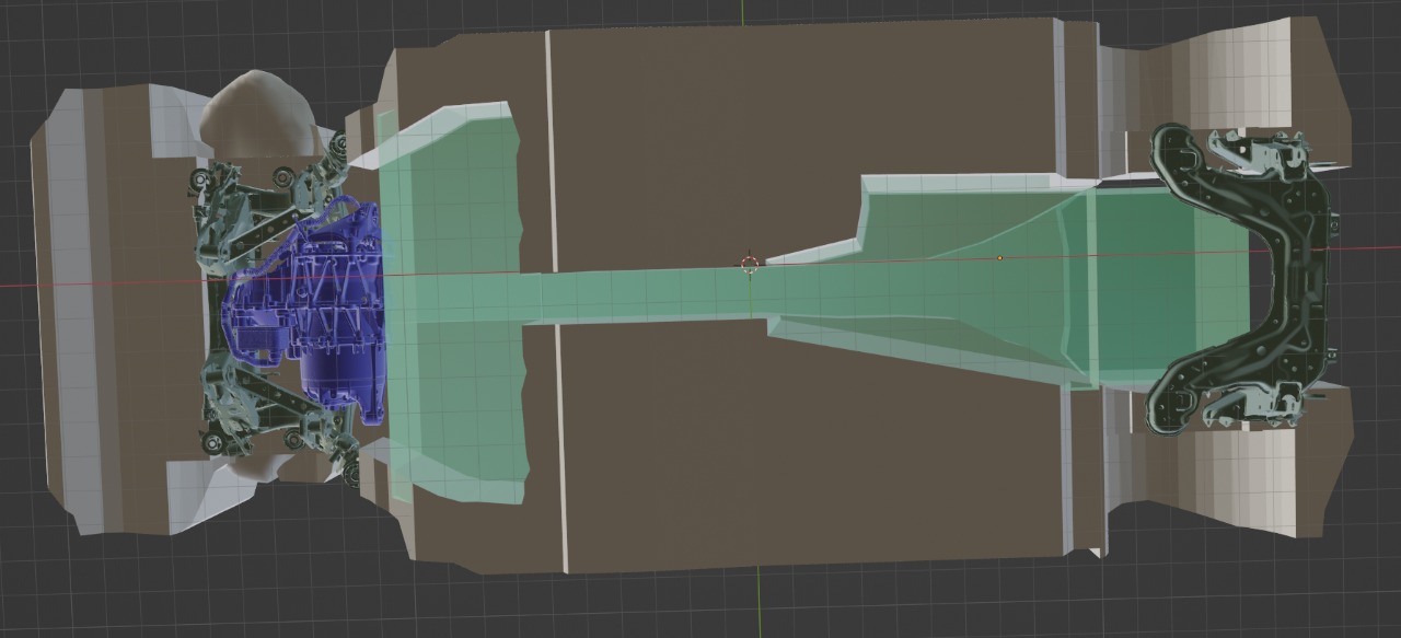
I spent some time today figuring out where the electric motor is going to go. This is unfortunately a prerequisite before I can figure out where and how big the battery can be--it doesn't make sense to plan batteries only to find out that the motor is occupying your entire volume!

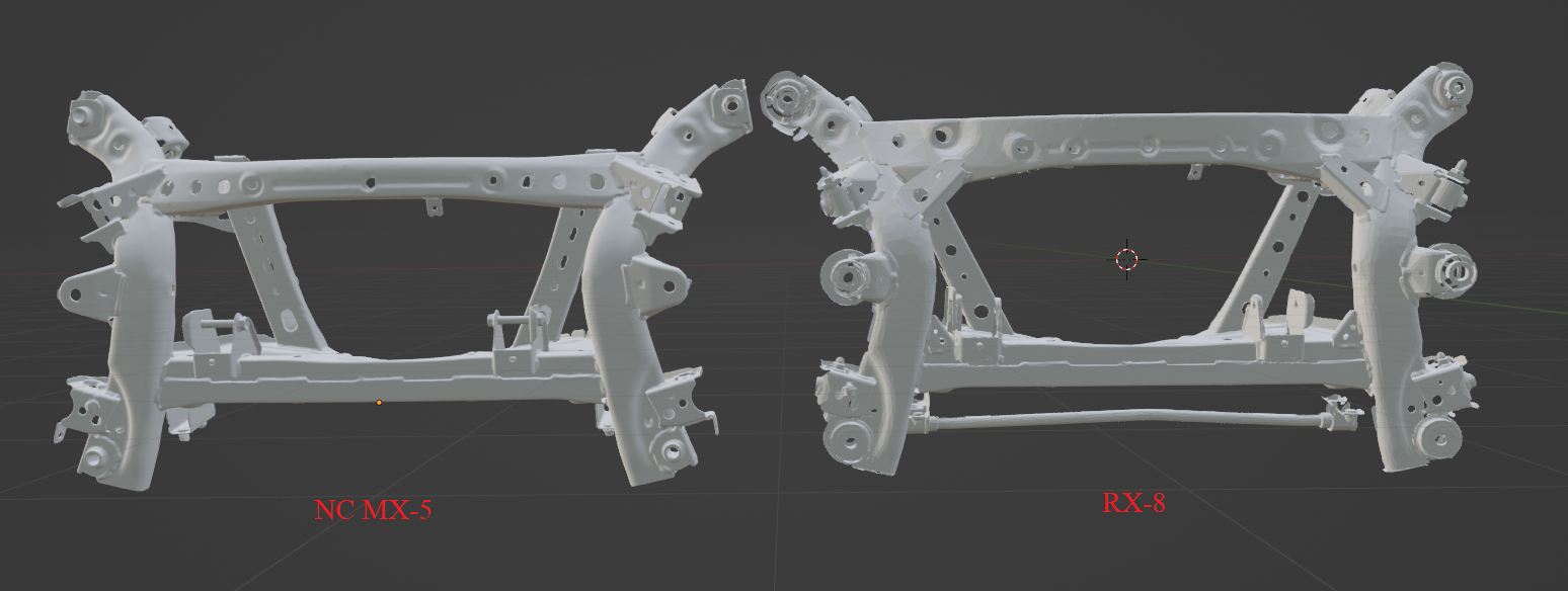
I'd like to, as much as it is possible, put the electric motor directly where the differential of the RX-8 was, which may involve some rear subframe stuff. I have the part drawings and some measurements, but what I really need to bring everything together is a detailed 3d model of the subframe. Someone has scanned their NC (gen-3) MX-5 subframes and put them online, and I was hoping that they'd be equivalent (there are various forum postings for and against). I did some digging, and while the rear subframe is /extremely/ similar, to the point of being bolt-on compatible, it's not 100% identical to the RX-8 rear subframe.

Spot the differences...

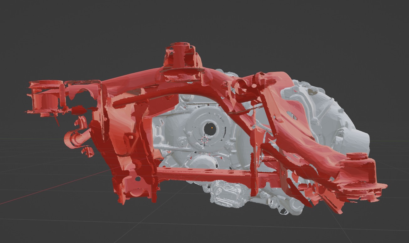
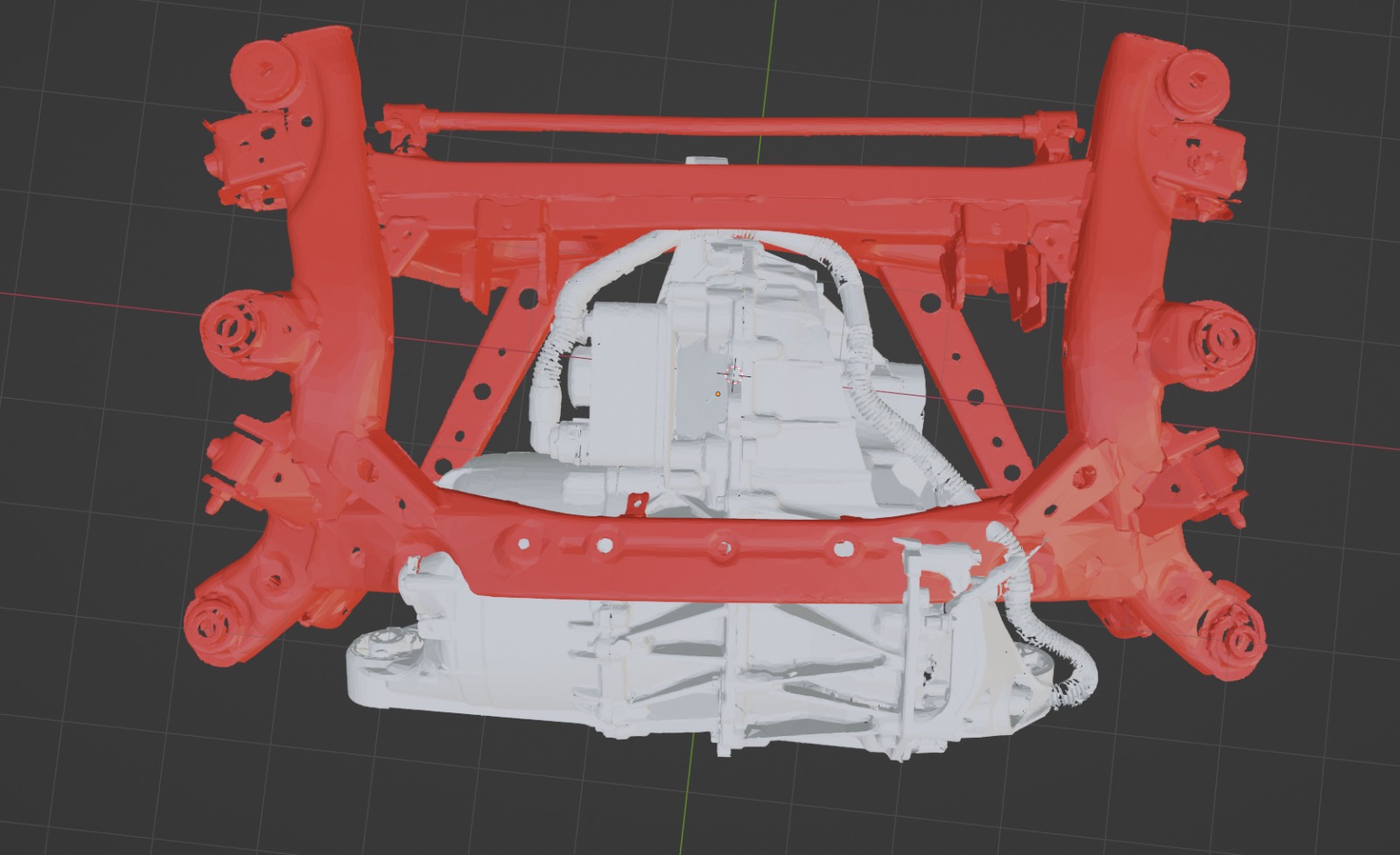
Thankfully, Andrew from Keisler Automation is super friendly, and sent me a copy of his 3d scanned RX-8 rear. Keisler sells bits and complete kits to swap a GM LFX V6 into an RX-8, and I noticed on their web store front for their rear differential kit something that looked like a 3d scan, so I asked nicely :)

It looks like the Tesla Small Drive unit wouldn't fit without quite a lot of modification, both to the subframe and the bodywork of the car. It'd also stick out the bottom, which is no bueno. The model 3 rear drive unit, however, seems to be possible and even reasonable.

Side view Top View

Body Shop Manual

Body Shop Manual

After I spent the time under the lift, I realized I was missing some measurements. After some googling, I stumbled across the body shop manual... which meant the whole tape measuring exercise was unneeded. Still glad I got under the car, though, and the pictures help me put things into context.