I've been a busy bee, flitting around to various places to source pieces for building up the battery packs. I managed to gather quite a few of the important pieces before 2023 came to a close, but didn't manage to find the time to post an update. In no particular order:
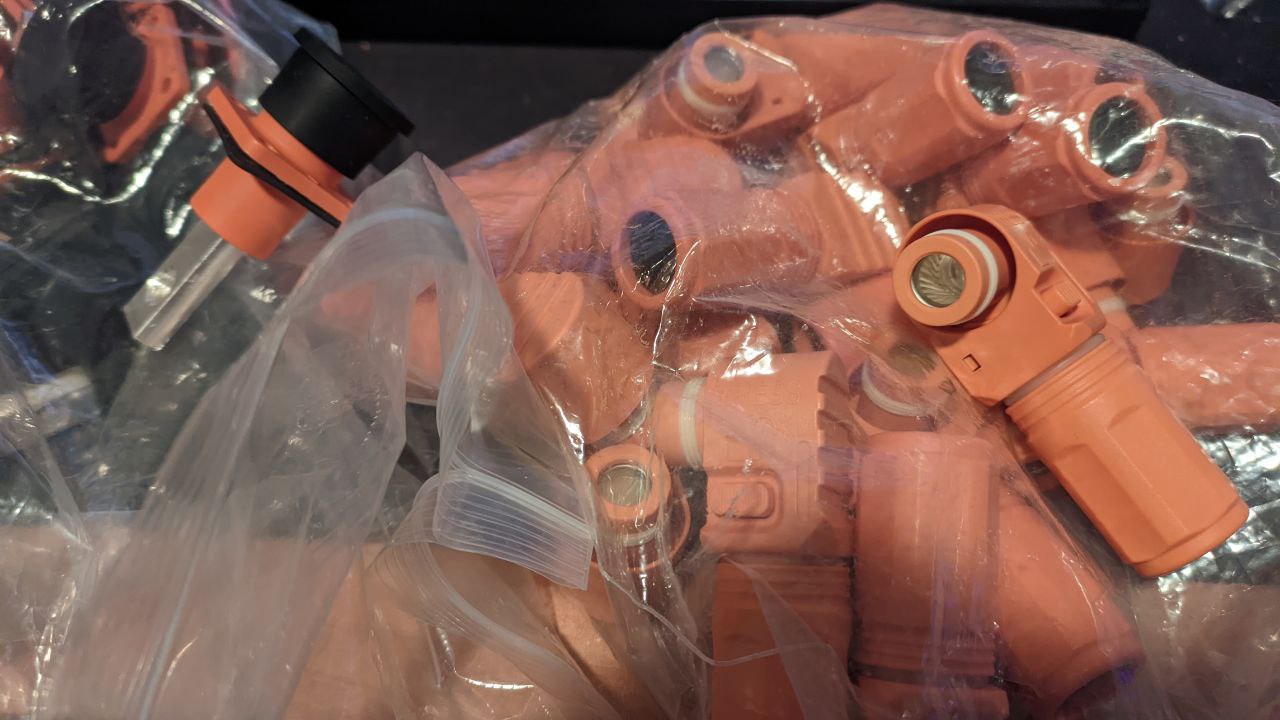
High-current connectors
These snap-on connectors are perfect for connecting power through the various battery packs and to the end devices. They're vibration and water-proof, and can handle quite some current. Both the connector and the socket are coming from JNIcon in China.
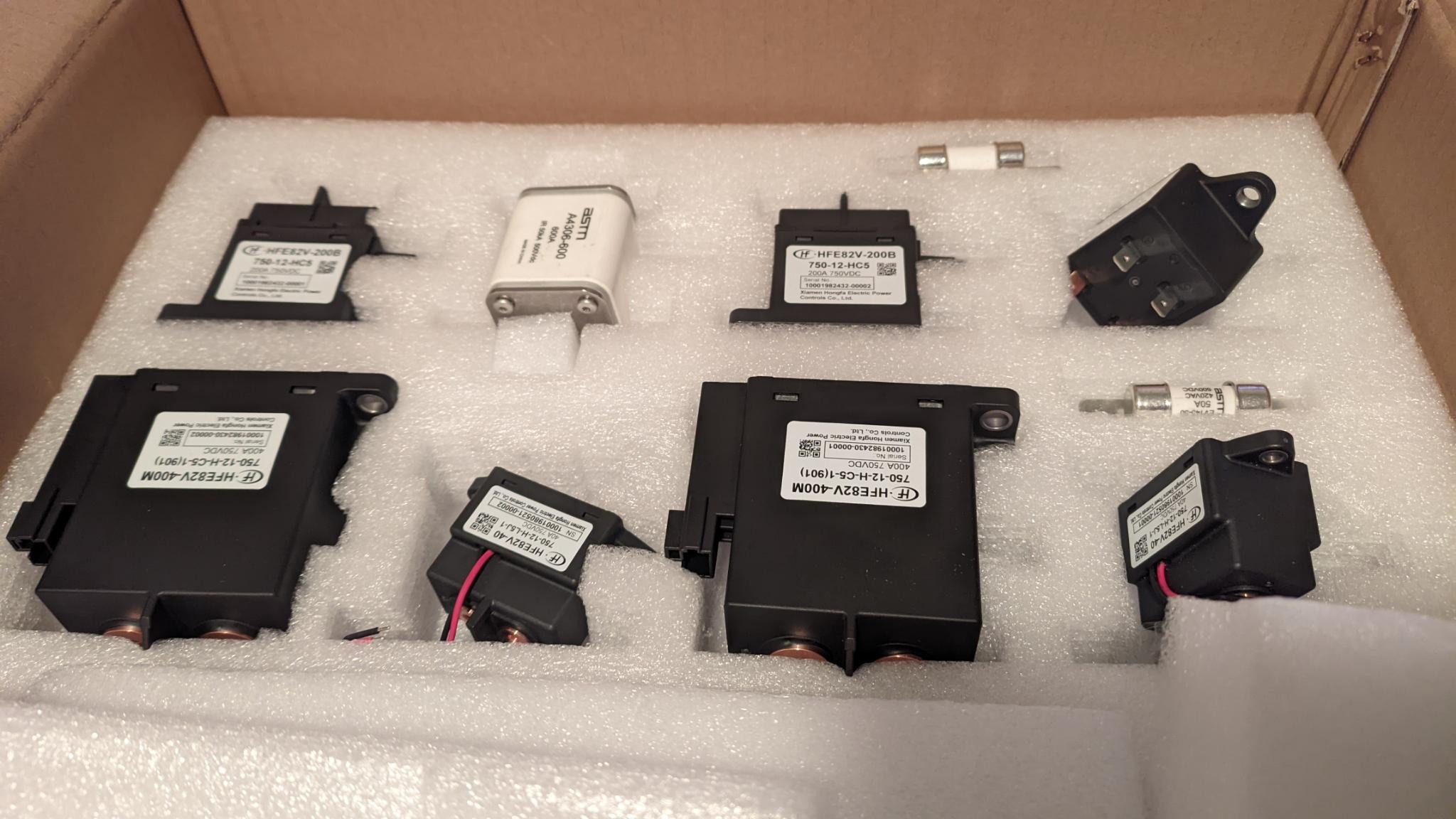
High-current fuses and DC Contactors
This is a massive fuse:
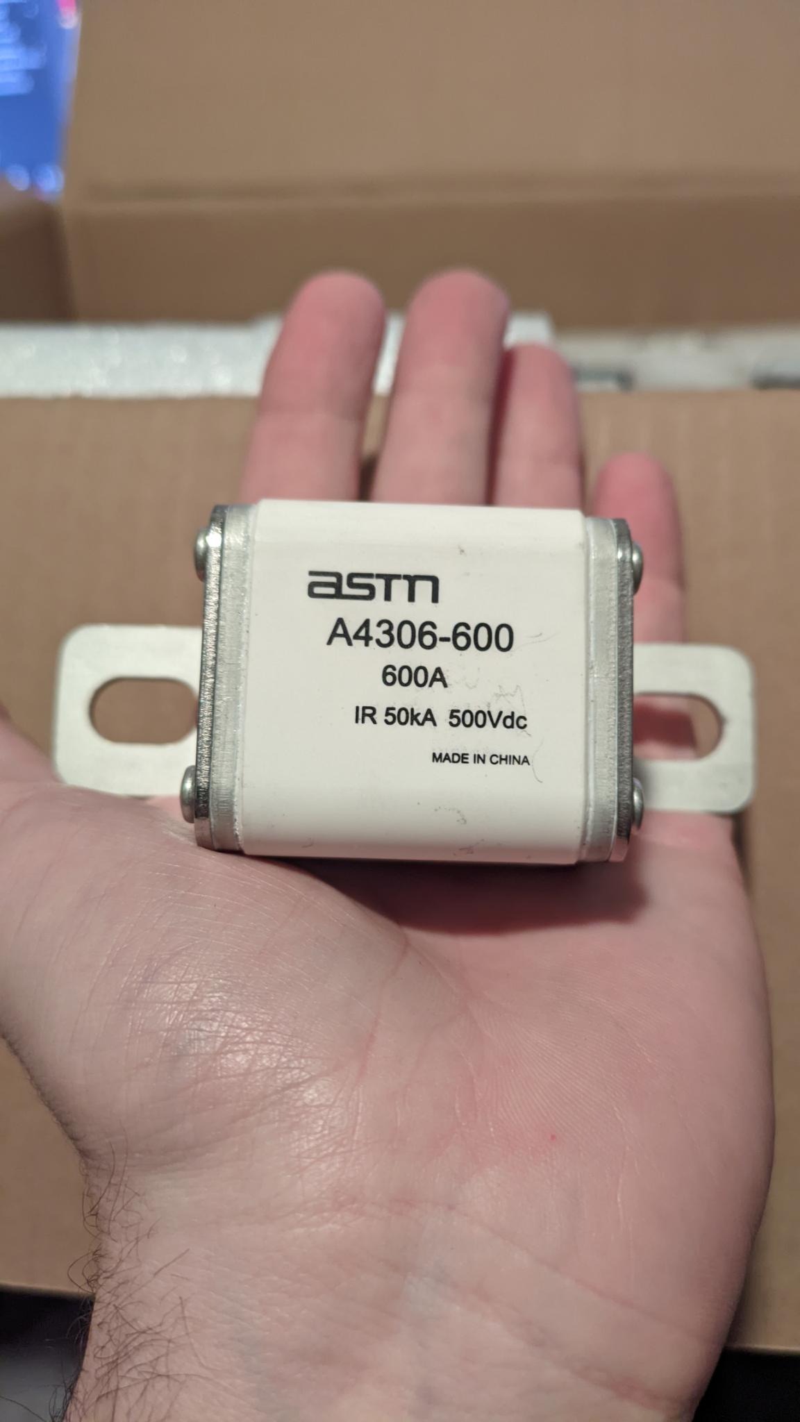
Which is good, as it is one of the main fuses for the system, needing to be capable of interrupting >550A at >400V in the case of a dead short of the traction battery.
The other HV fuses are a bit smaller, protecting various subsystems like HVAC and the OBC. The main contactors (think like a relay, but for DC) are even bigger than the fuse! The big issue with switching DC is, in contrast with AC, there is no "zero" crossover point, so attempting to disconnect the circuit under load has the potential to start a spark which will self-sustain and cause big issues. These contactors are responsible for connecting and/or disconnecting loads to the traction battery.
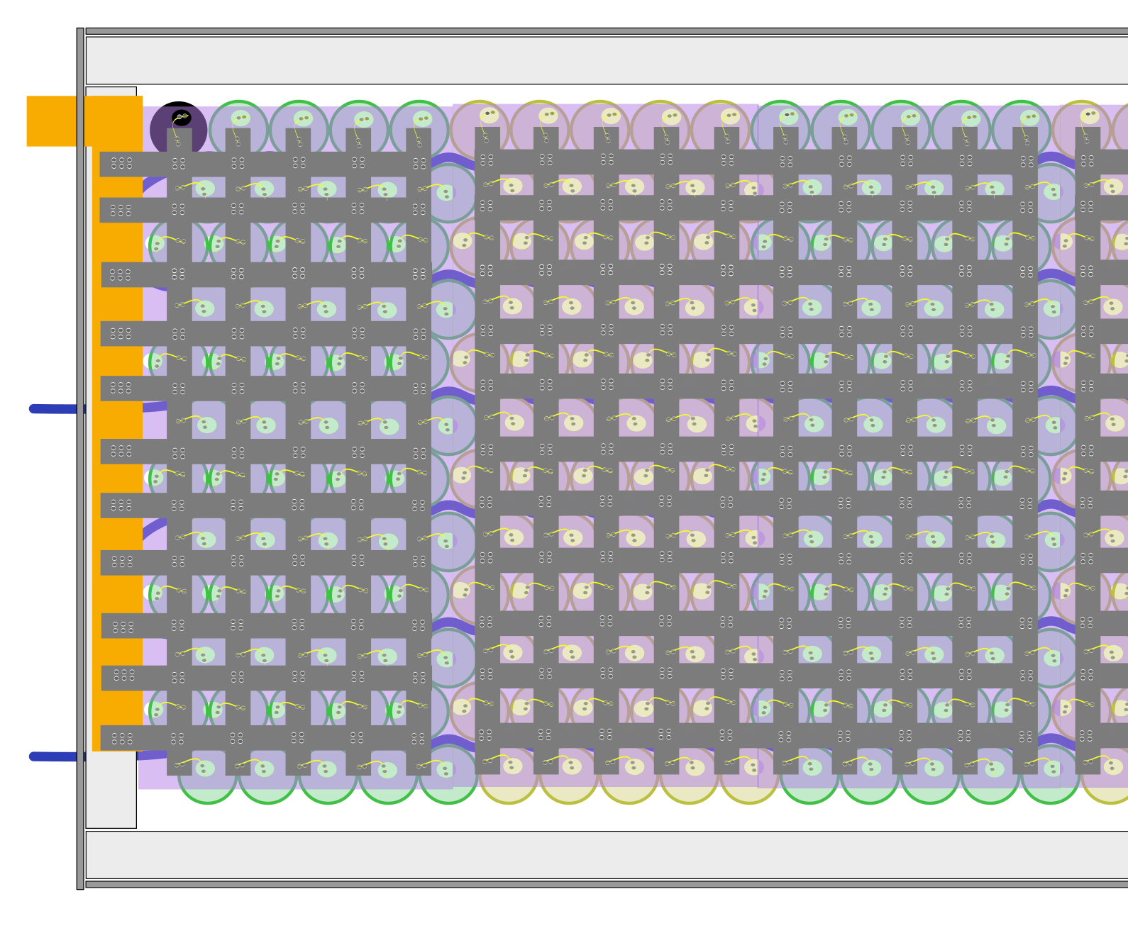
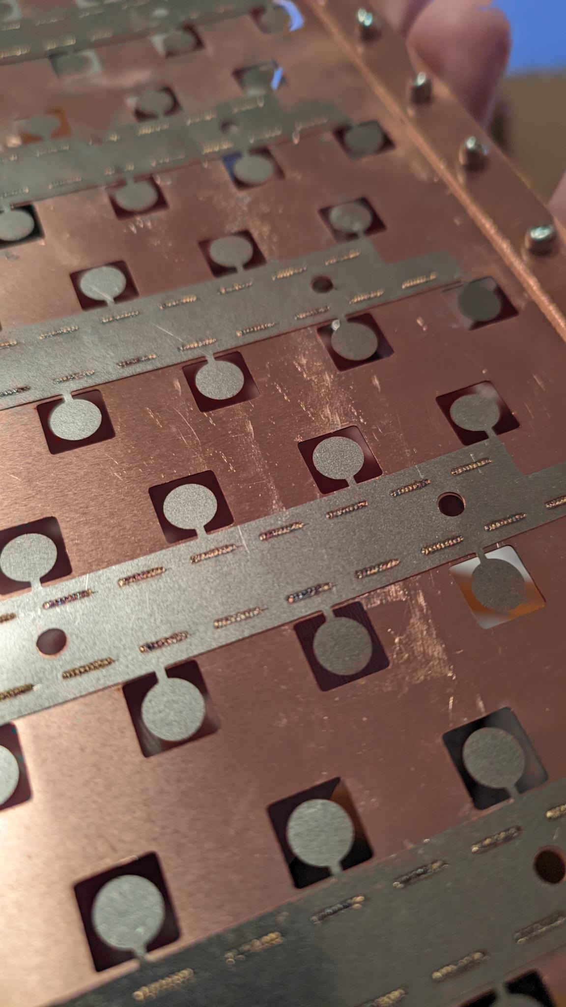
Copper/Nickel Hybrid Collector Plates
I originally was planning to build the battery packs up with nickel strips, with the cells being connected to the grid of strip with small fuse wires. After running the numbers, however, it was clear that not even the thickest, widest strips of nickel metal had the required ampacity to carry all the current I was asking without getting really quite hot. I will probably do a dedicated post for the design of the battery pack at some point, but for now know that I designed a custom hybrid copper/nickel plate for the battery packs which combines ease-of-welding with a high ampacity. Bonus, each cell has a small nickel fuse which limits things to <20A and should prevent a fire in the case of a single-cell short.
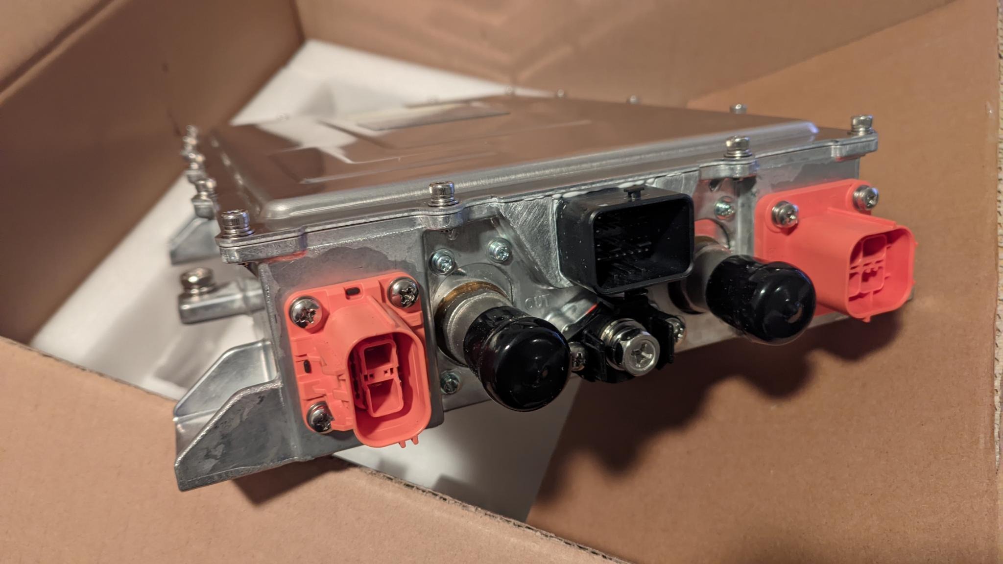
Onboard Charger and DC/DC
I will definitely have a whole post about this OBC from Kanchan. It's an onboard charger with a maximum of 6.6kW (single-phase) from AC, as well as a 2kW DC/DC to provide the 12V from the traction battery. It's liquid cooled and smol
Next Steps
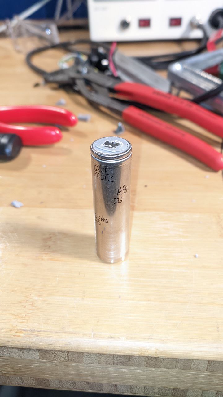
The biggest next step will be automating the harvest of the raw cells from the donor packs... hopefully a big update on that coming soon. Also looking into the motor control concept, which will be a roadtrip, and a few other bits and bobs outstanding... The RX-E will drive in 2024!
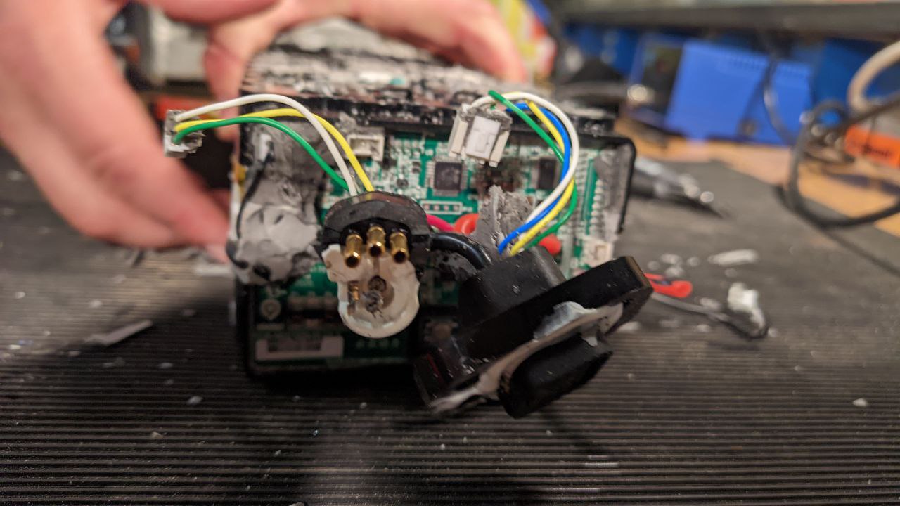
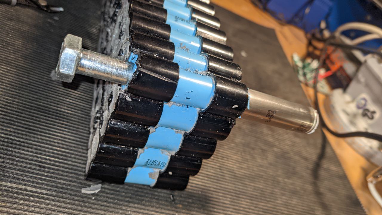
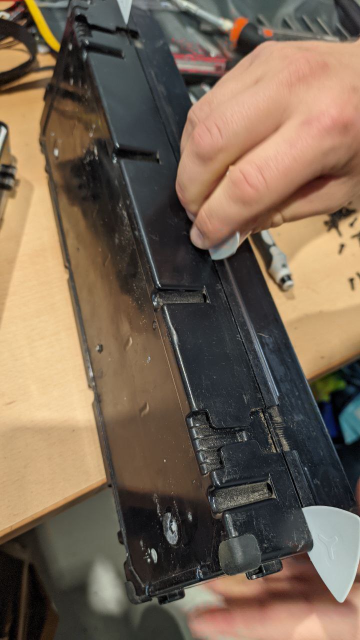
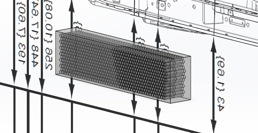
 With the top removed, a first look at the cells and their arrangement, each one neatly encased and connected.
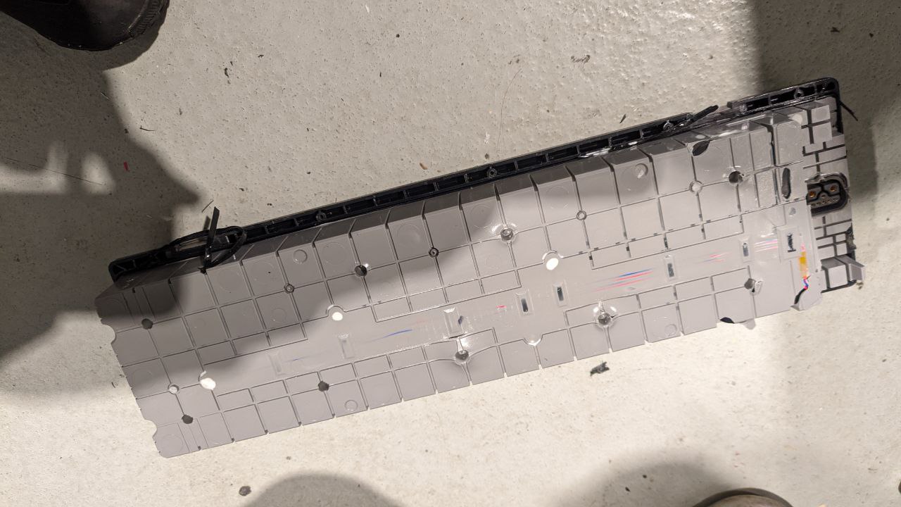
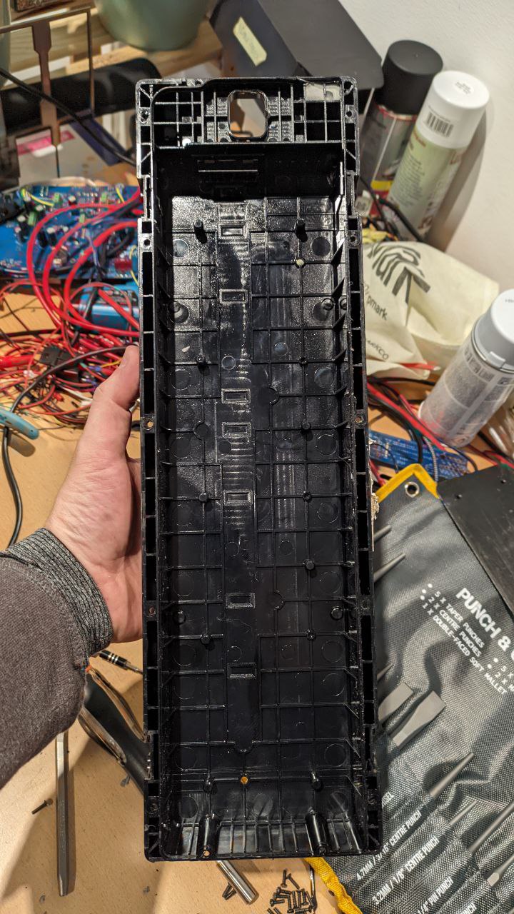 The lone top case.
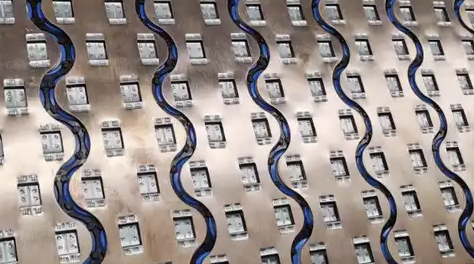
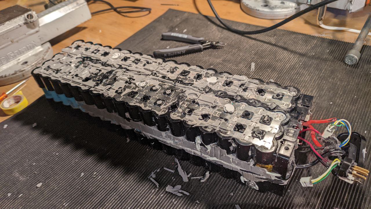
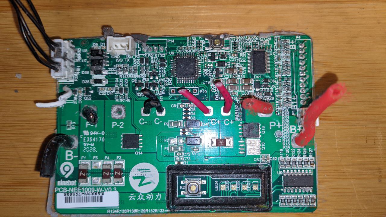
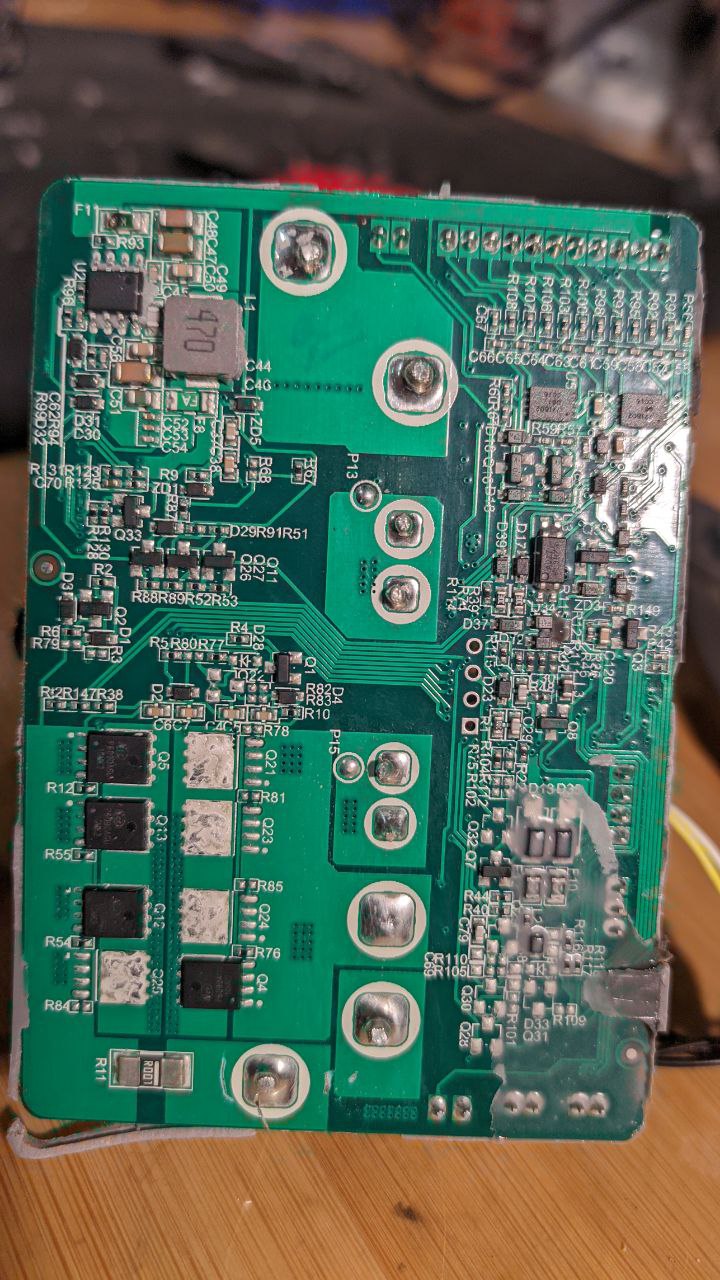
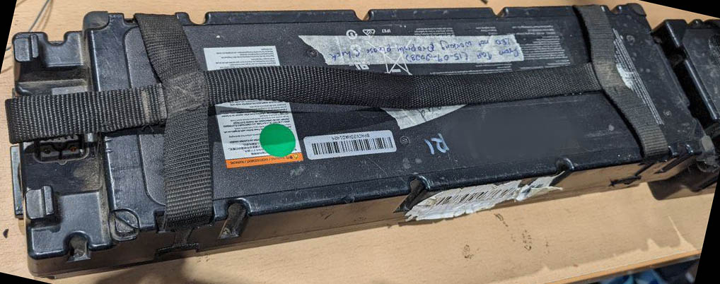
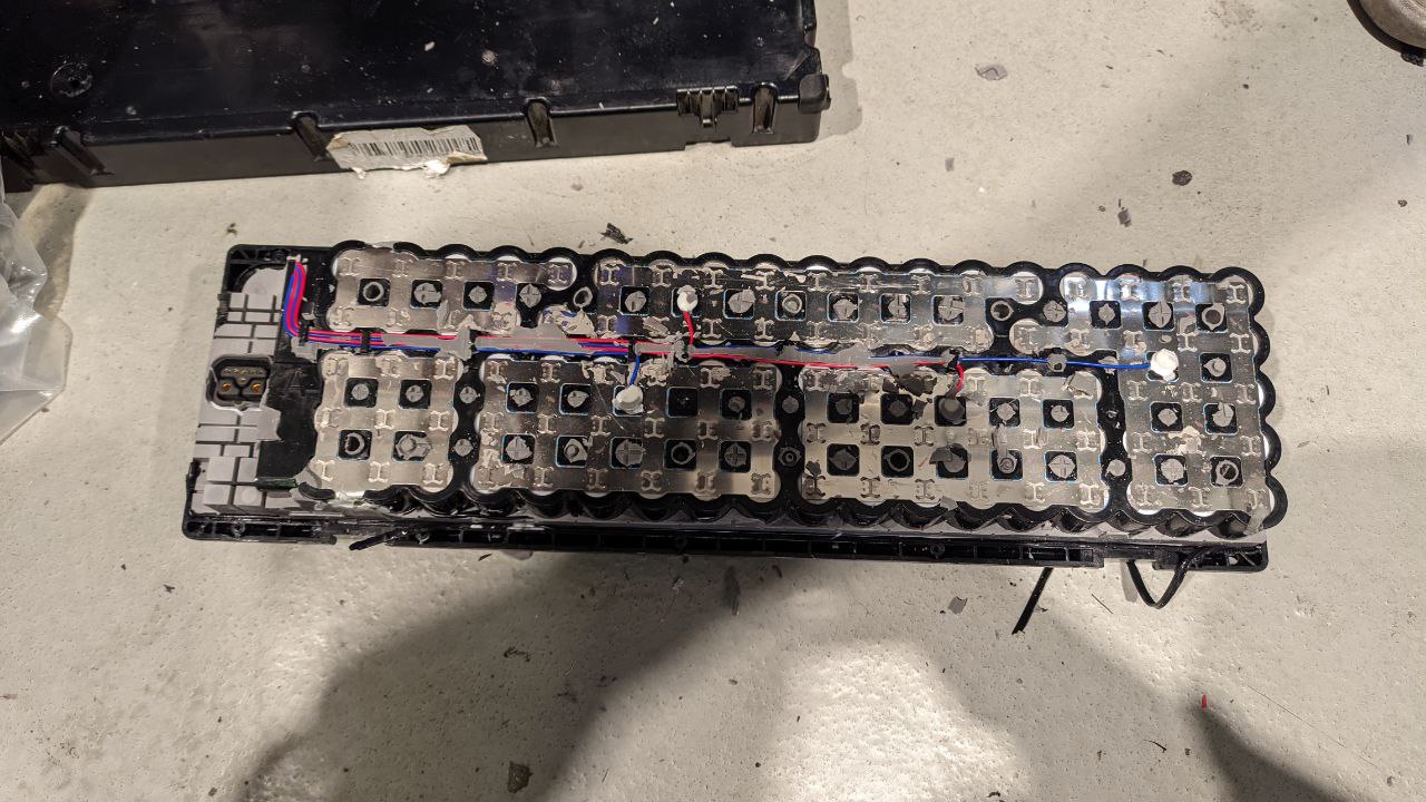 Removing the silicone reveals the electrical architecture of the battery pack.
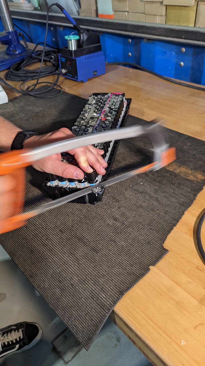 Sometimes you just need a hacksaw...
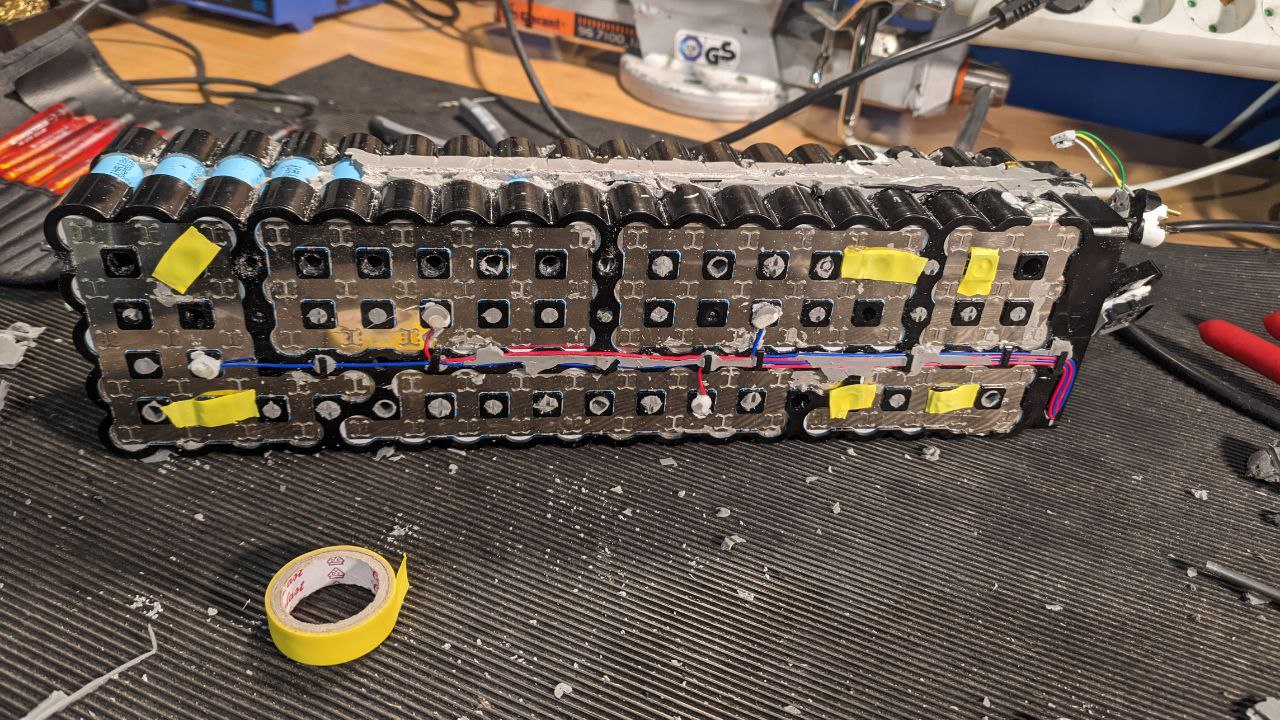
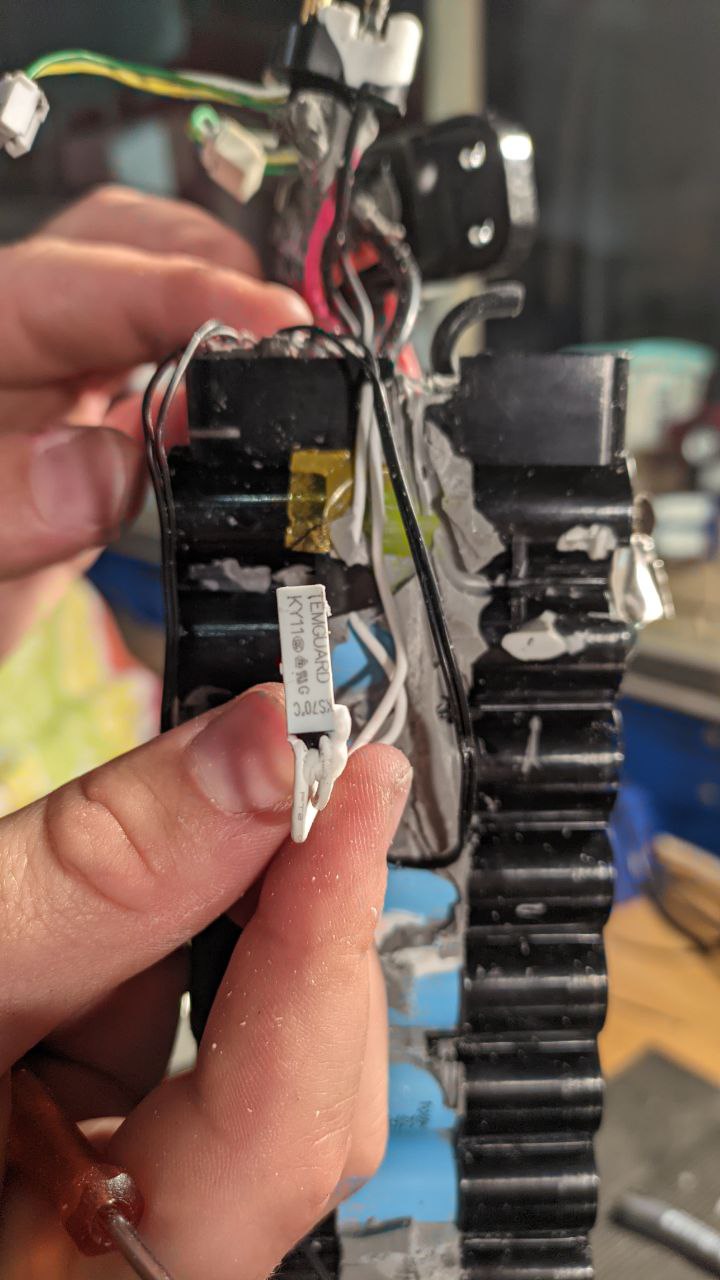
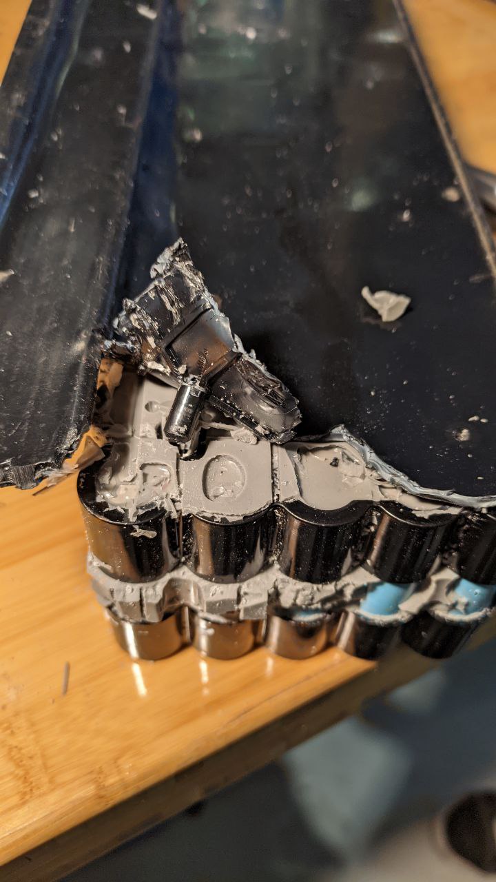 Peeling back the lower plastic
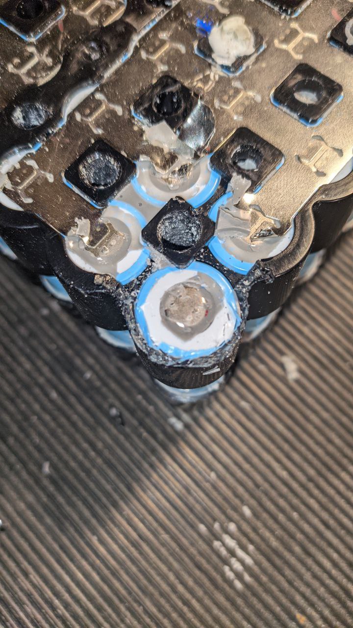
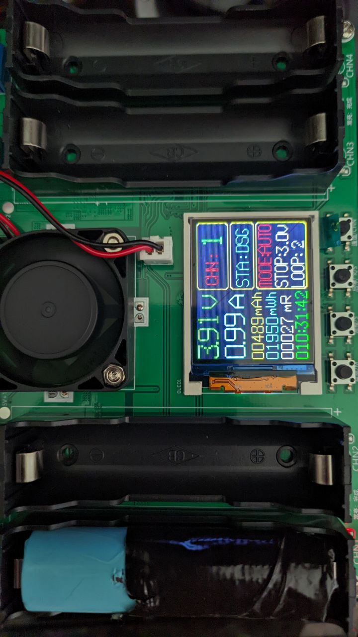
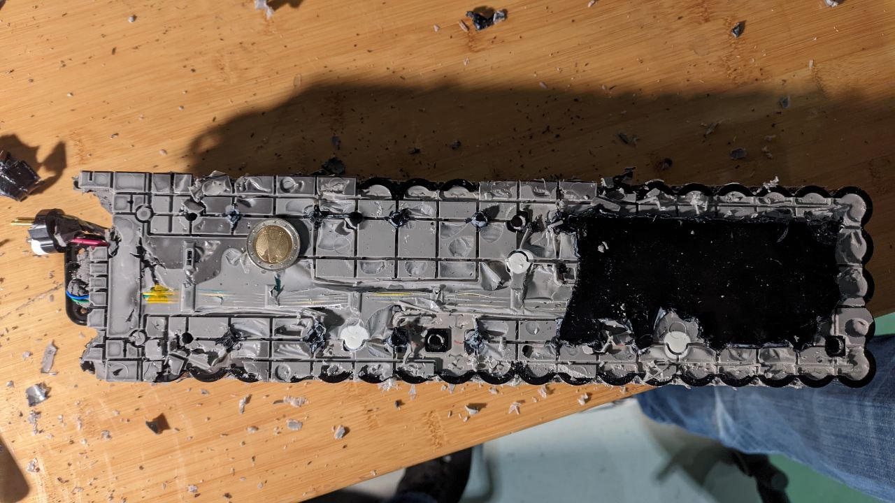 Finally, the battery pack stands bare. We ran out of time, but did manage to verify that all the cells are okay--the groups measured out to 3.7v and the whole pack was still at ~36V