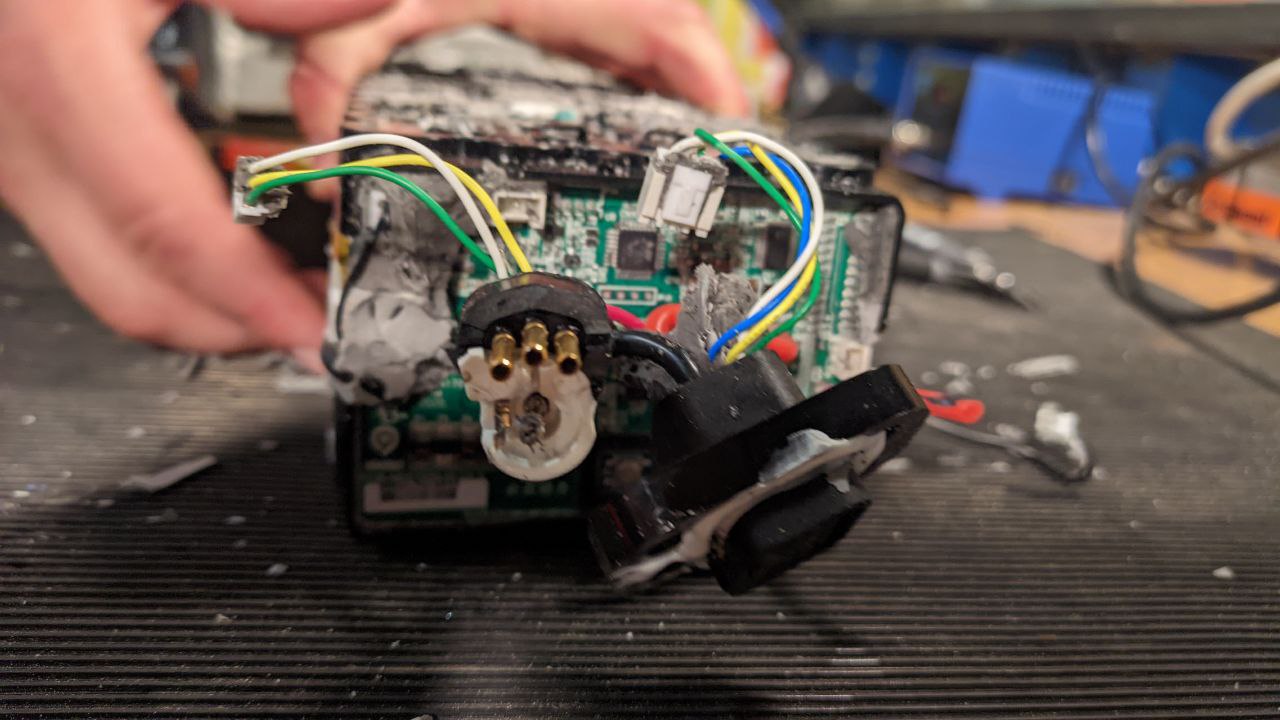
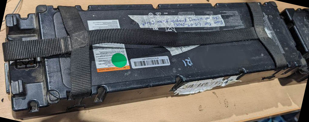
It was past time to get back at the battery module, to figure out how I'm going to harvest all the cells before I even consider how to put them together into a new module. Together with my battery-massacring compatriot, we resolved to finish the job. When we last left our patient, it looked like this:
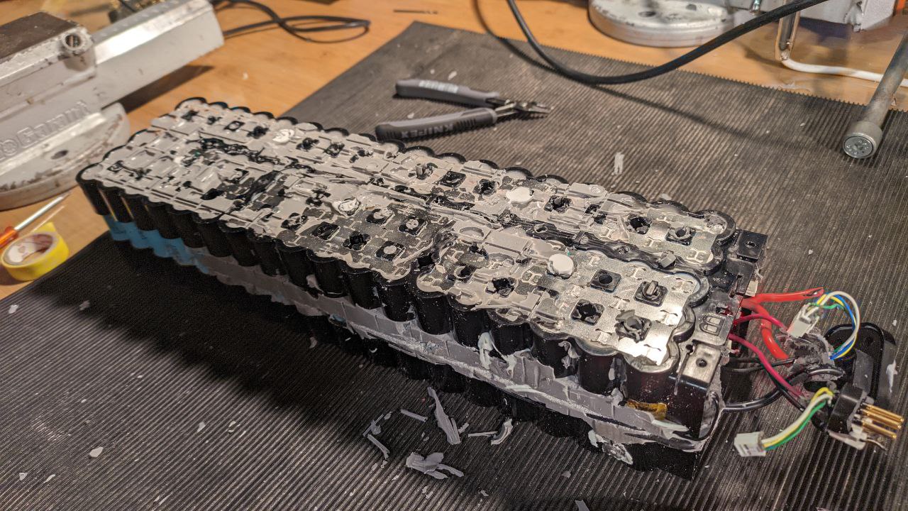
With the assistance of a drill press and a 5.5mm bit, we reamed out the rest of the spaces between cells. It turns out, the two parts of the shell are screwed together!
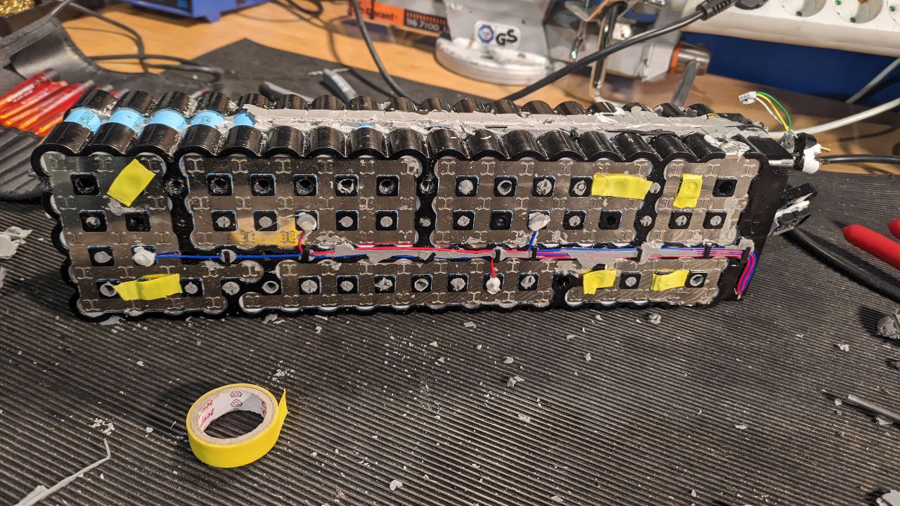
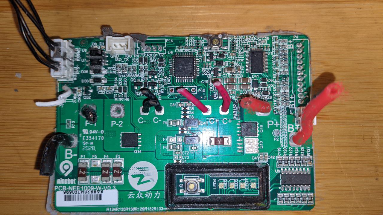
It seems every second hole is an opportunity for a screw (some marked with yellow, above). However, even after reaming, the shells still wouldn't come apart. We took a detour and popped out the BMS Board...
Which was hiding under a mass of filler materials. Here is the dead BMS, front and back, freed from its silicone prison.
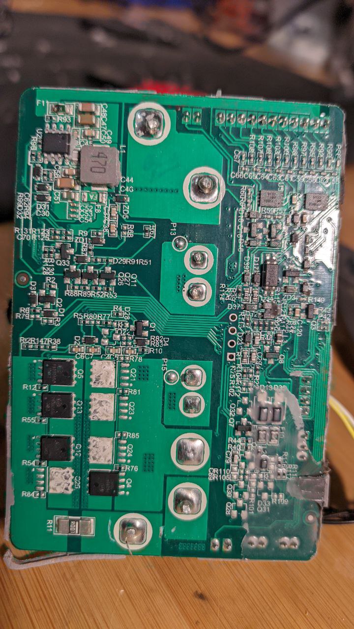
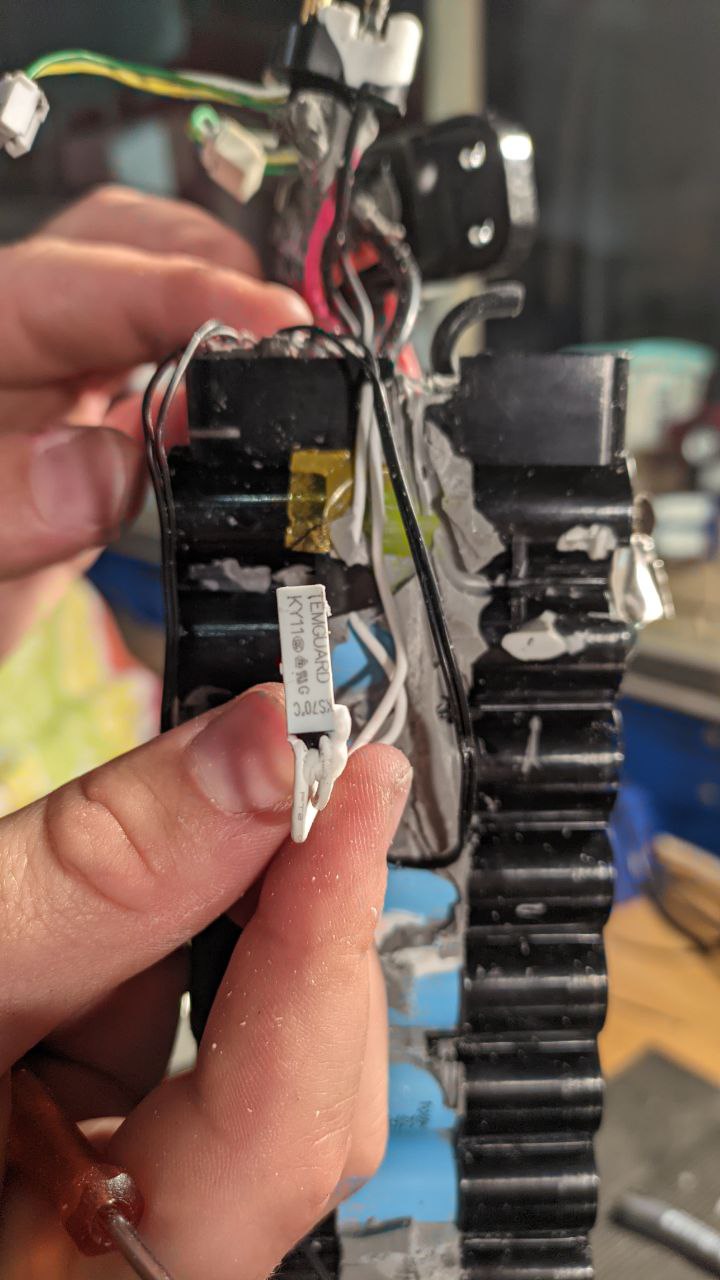
If I cared at all about the BMS part, I'd look at the STM32G0 a bit closer... but I don't :) There was a very interesting thermal fuse included:
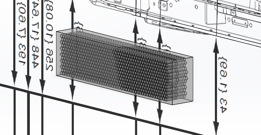
It was then that the scope of the task made itself readily apparent:
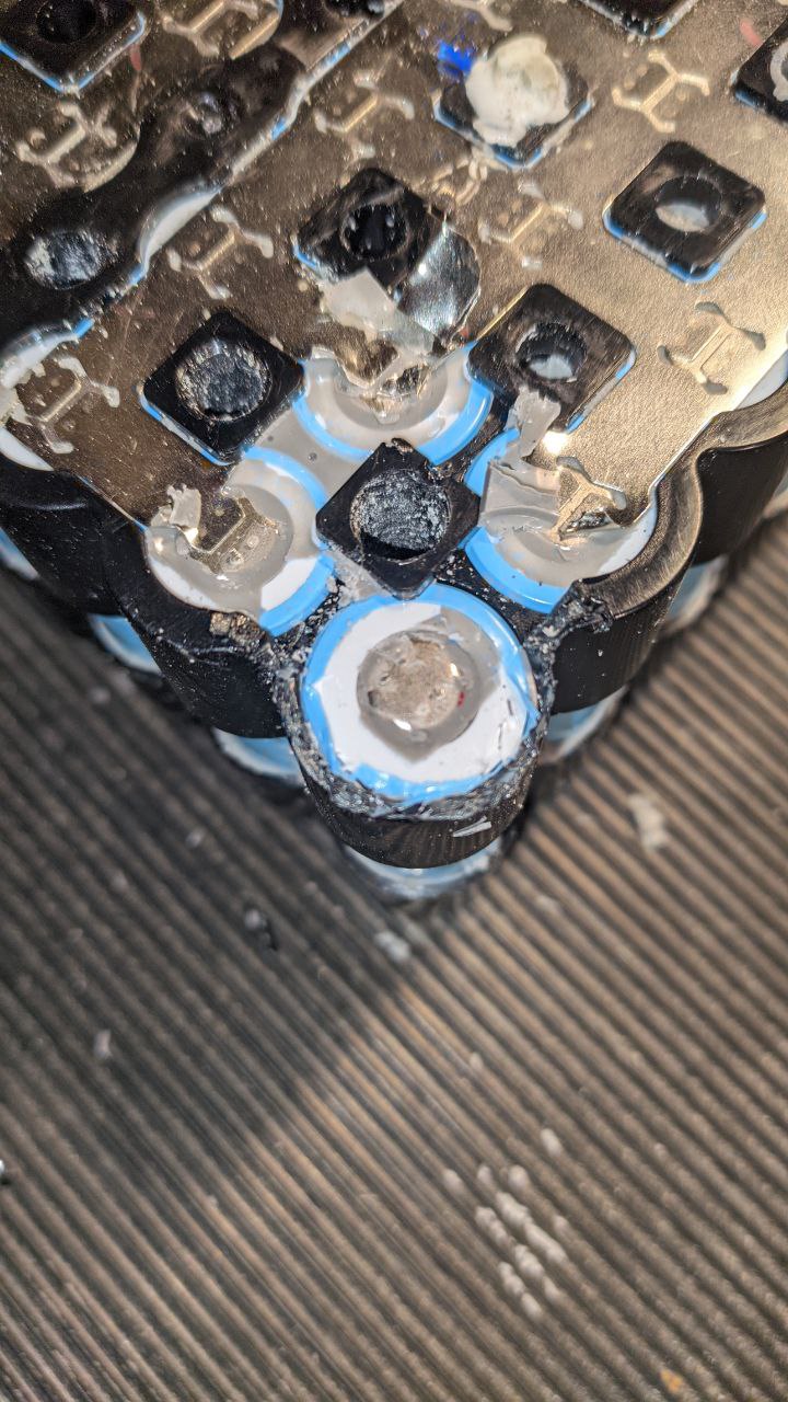
The battery pack is designed in such a way that it goes together quite easily, and is extremly rigid and robust against vibrations and other mechanical stress. The nickel collector plates are likely welded after the frames are on, as the nickel plates form part of the retention mechanism for the cells (together with a little bit of plastic which overlaps each cell). This will be a nightmare to disassemble with only hand tools.
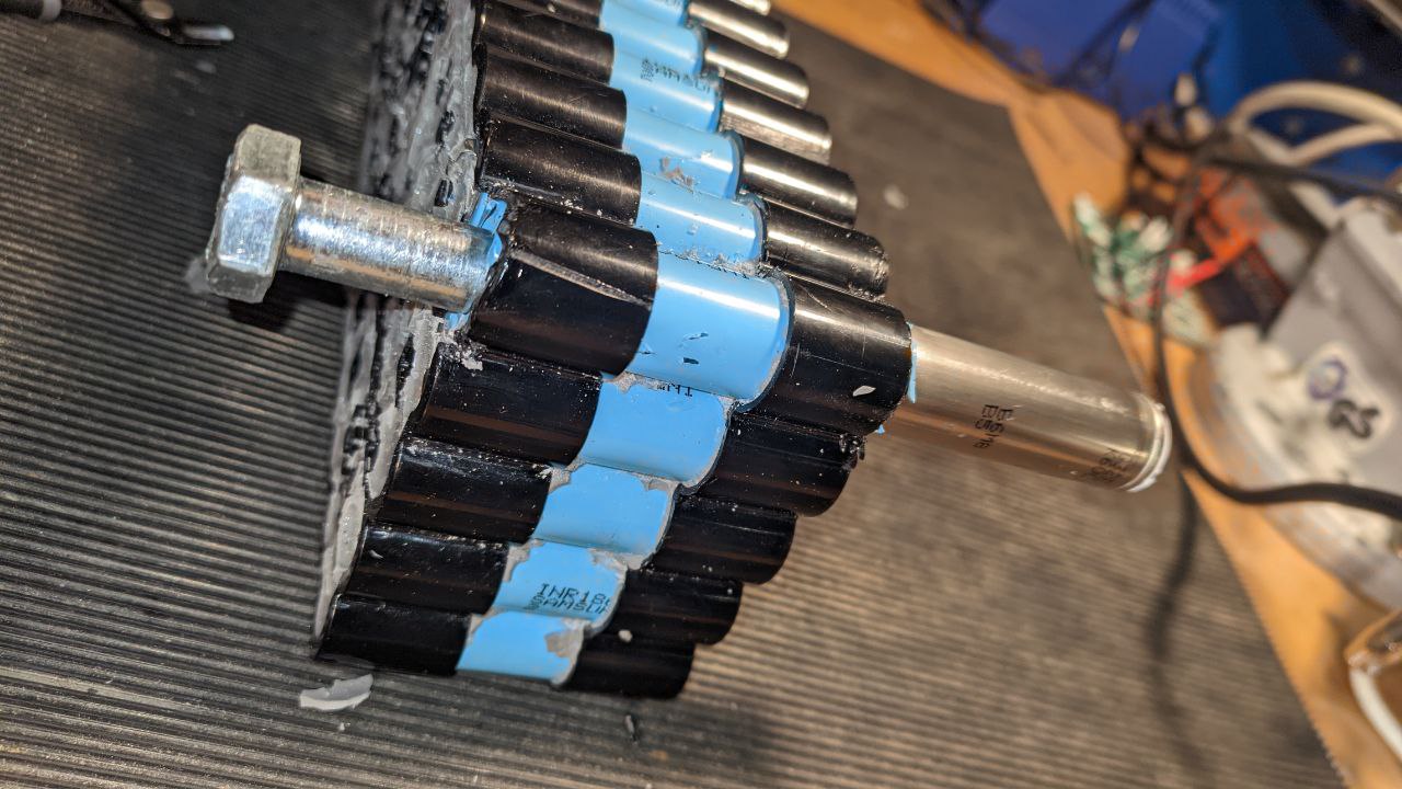
Nevertheless, we would not be denied our prize. With some diagonal cutters and some very careful surgery, we were able to cut the supporting material away from one of the cells in the corner and then very carefully tap it out with a bolt.
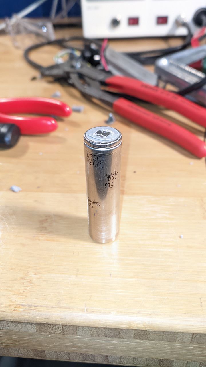
I took the cell home and threw it in the battery cell tester for a few charge/discharge cycles:
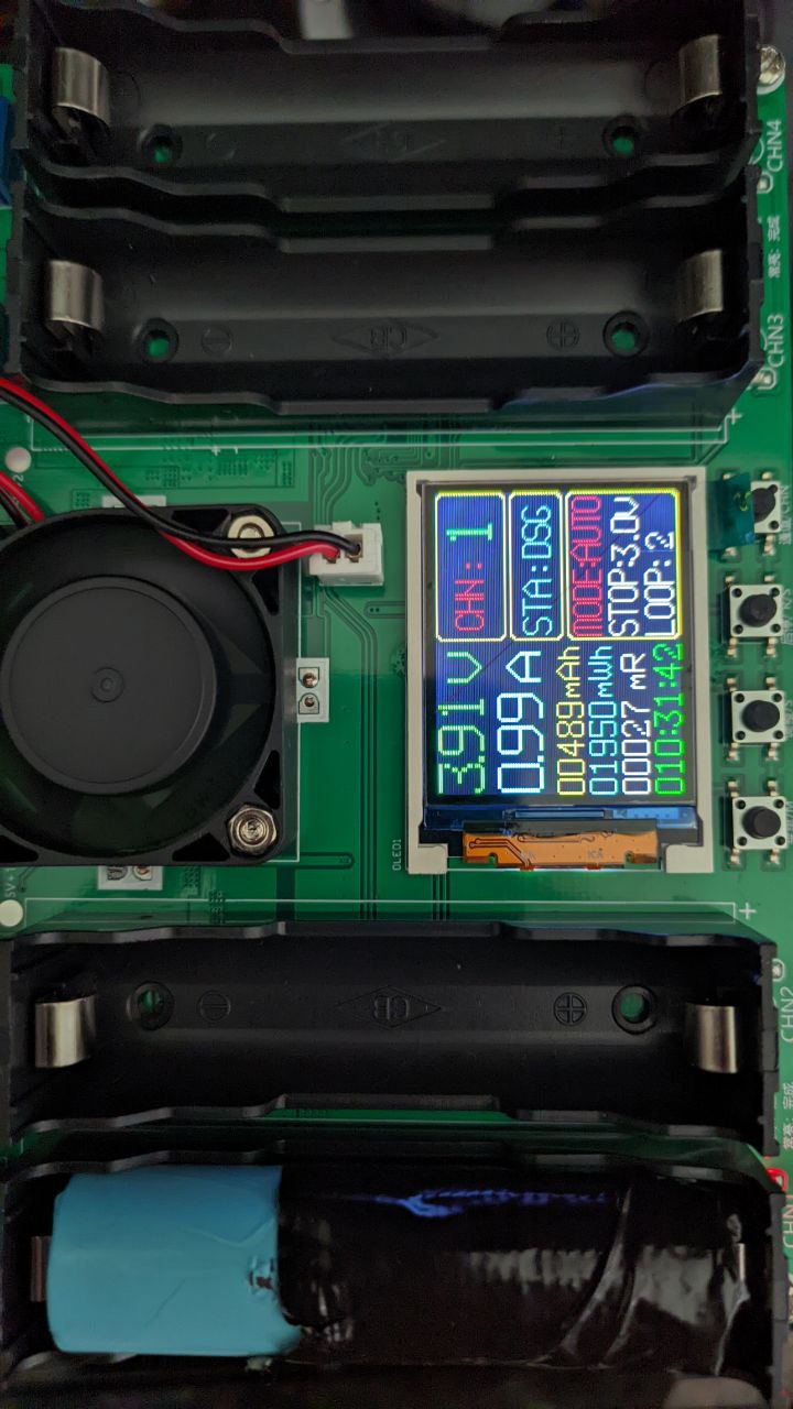
27 milliOhm is within the 35 max specified for the battery, and once the testing cycle is complete we'll see how much capacity is left--I am expecting quite a bit.
As to how to deal with the other cells and battery packs... well. They have to go a bit more smoothly. In the meantime I will get some replacement insulation sleeves and rings to ensure everything is in tip-top shape for the eventual pack construction.
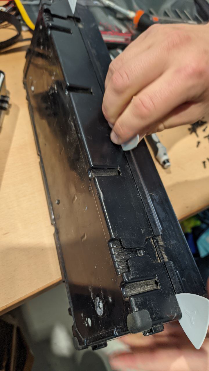
 With the top removed, a first look at the cells and their arrangement, each one neatly encased and connected.
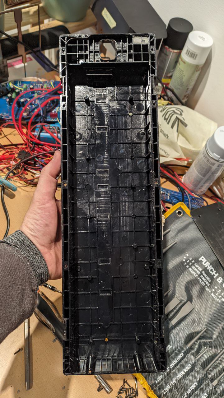 The lone top case.
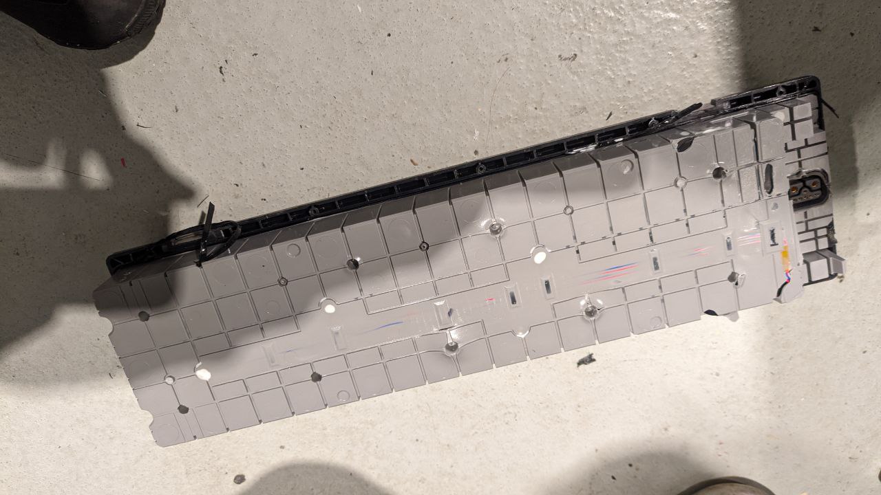
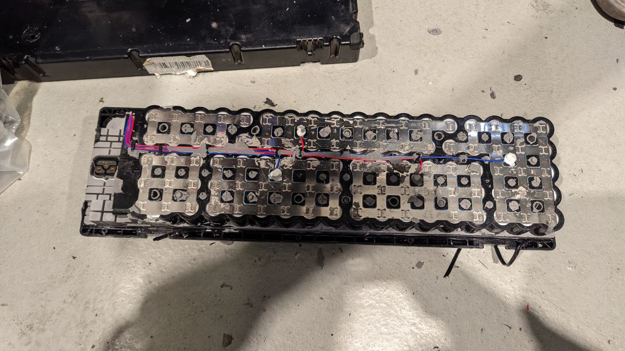 Removing the silicone reveals the electrical architecture of the battery pack.
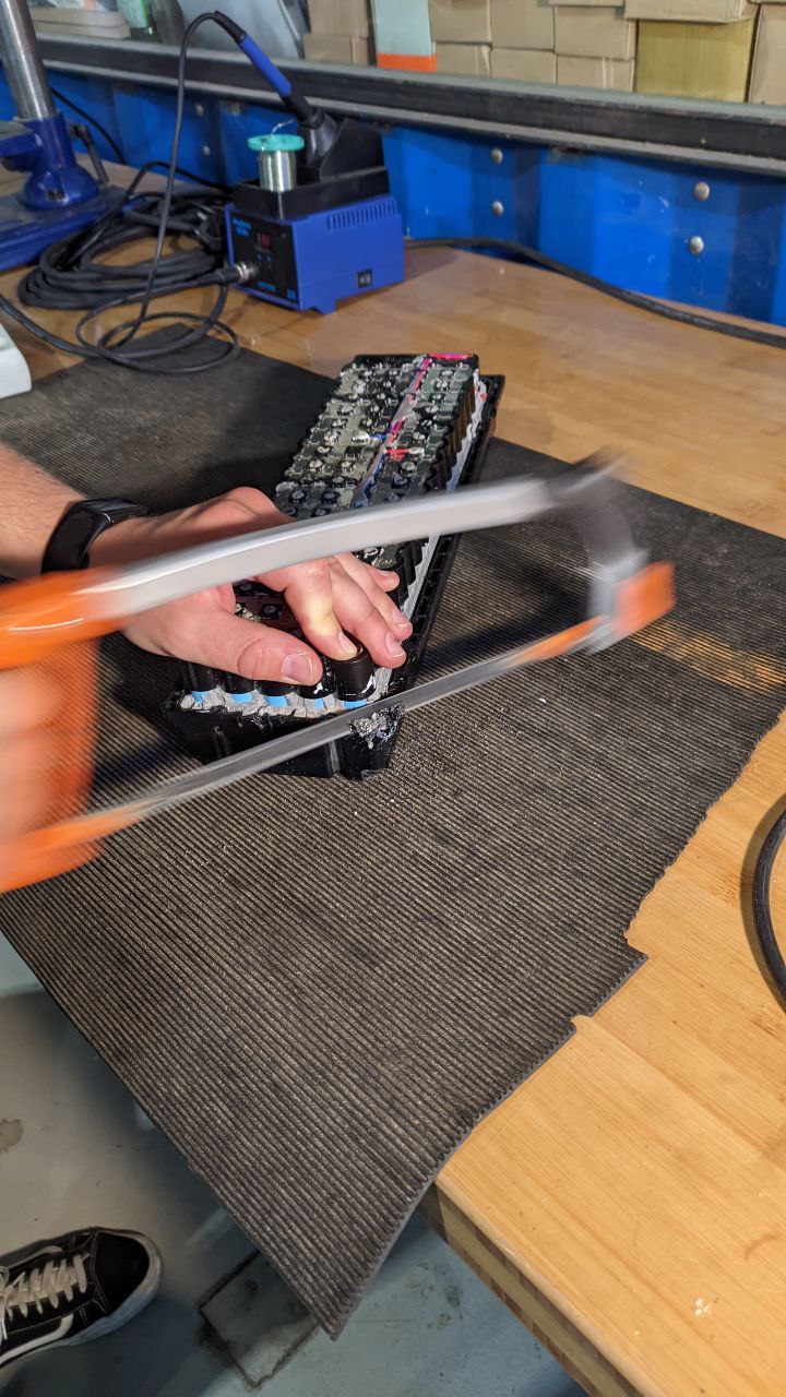 Sometimes you just need a hacksaw...
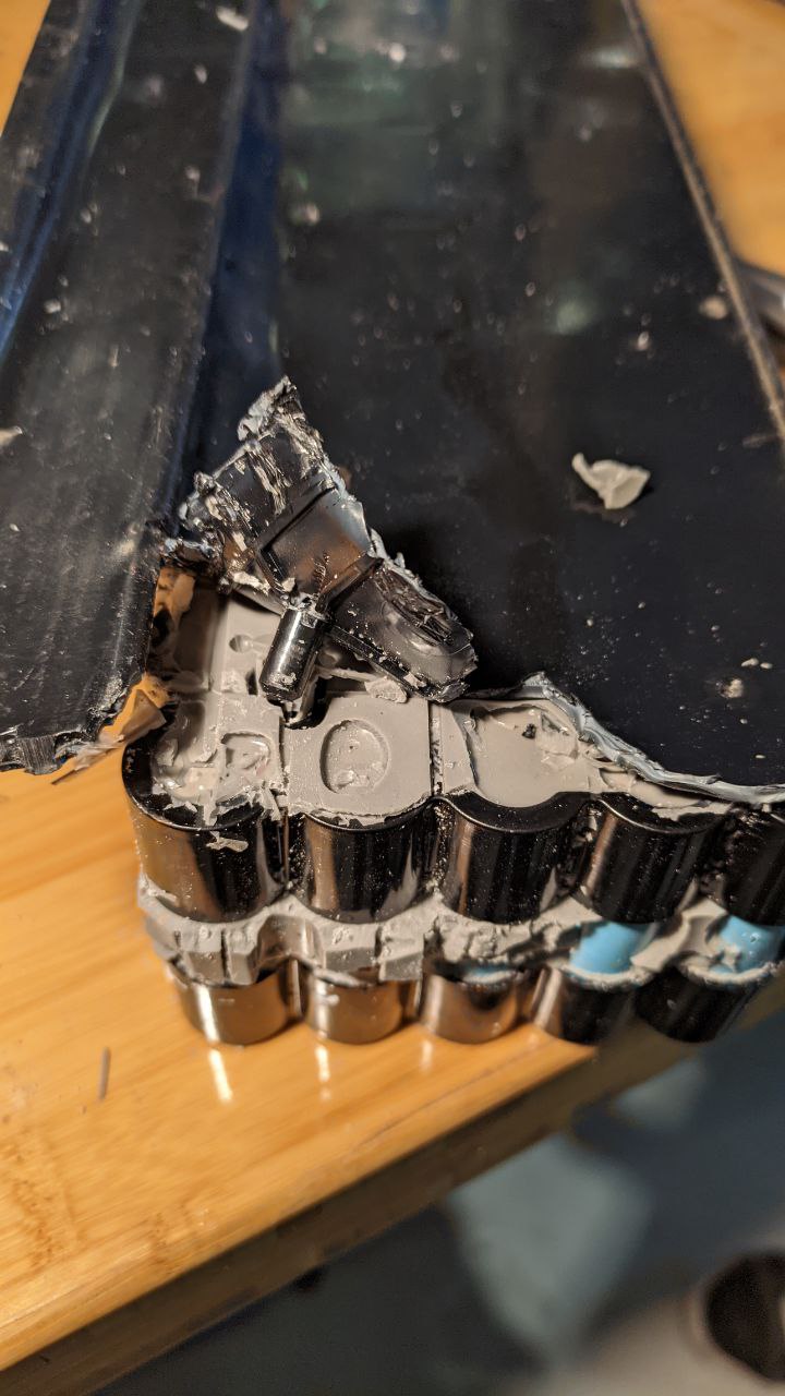 Peeling back the lower plastic
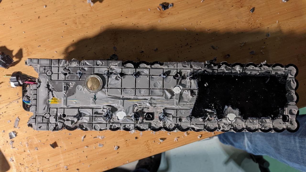 Finally, the battery pack stands bare. We ran out of time, but did manage to verify that all the cells are okay--the groups measured out to 3.7v and the whole pack was still at ~36V