More Battery Pack Musings

More Battery Pack Musings

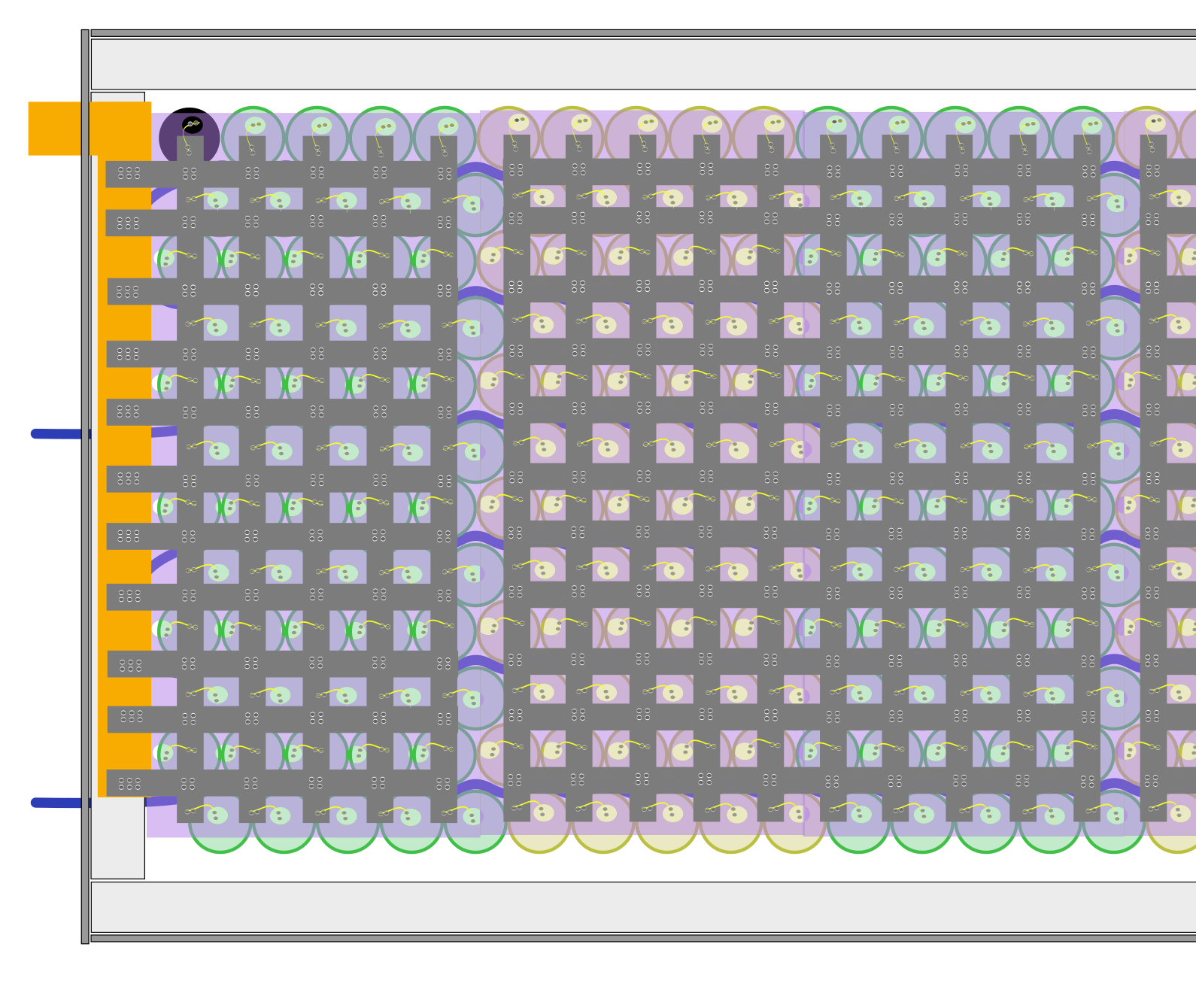
What has 5,000 welds and 600 tiny fuses? One battery module. I drew up a schematic for the module to get an understanding of layout, and it looks like it will be the easiest to do 10 x 60 with a somewhat offset pattern, to accomodate the heat exchanger. (see above)

This has the downside that nickel strips simply don't carry enough current; using 8mm x 0.3mm nickel strips in this way, the pack would only be able to supply about 150A before overheating. Thankfully, there are some options here, I found a supplier that makes hybrid nickel (weldable) copper (high current) solutions, and they should be able to make something perfect.

combo of copper and nickel

Apart from that, I thought it might be good to have an aluminum frame for the module that the PETG panels are attached to. And I can use laser-cut PETG panels as cell holders, also.

70mm2 copper wire as collectors for the high voltage and bob's your uncle.

Let's talk (more) about batteries

So, with some additional time to muse, I am definitely going to split the batteries into 10S60P modules. There are some good reasons why:

  1. 10S is only 42V max, which means that when a module is taken out of the vehicle (or being built) it's low voltage and doesn't require any special handling
  2. One "row" of battery cells instead of two makes cooling simpler, as well as cell construction much simpler
  3. The size will be a bit smaller than 100cm x 8cm x 25cm, which lets me get a bit more creative with how they come together.

If the individual modules are separable, that will have to be considered with the BMS (it doesn't like groups being separated while plugged in...) but I think the advantages are worth it.

Additional thoughts:

  • Trumon makes serpentine heat exchangers designed for cylindrical cells. They will keep all cells in a pack within 5c of each other, and are probably a better solution than anything I was thinking of before with a cold plate--they're probably also more expensive.
  • I'll want some sort of "frame" to keep the batteries in. Since I have access to 3d printers with large print areas, I could print a frame, but I could also laser cut a frame out of PC or PETG (so long as they're flame retardant, at least B1/UL-94 V0)
  • I will also want some sort of thermal transfer material, as well as structural support internally. There are a ton of options here, from the ultra-expensive DOWSIL 3-6548 (A thermally conductive yet insulating silicone foam) and SEMICOSIL 962 TC to the really cheap silicone potting compounds, I will need to choose something. I want at least 2W/mK, and some voltage breakdown resistance. I looked at MG8327GF25 and GLPOLZ XK-S20.
  • I think PETG is a good material to make the "enclosure" out of, since there will be heat exchangers internally. PETG is shock and vibration resistant, it is fire-resistant, and you can work with it with a variety of tools. It's available in transparent, so you can see what's going on (visual inspection of cell fuses)
  • Given that there will be one layer, I'm pretty sure that using nickel strips internally will be fine, and then bonding them to a bus bar for the terminals. On one side, the strips will be directly welded to the cells, and on the other side, they will run between the cells and be connected with a fuse wire rated for 10a (roughly, 29ga tinned copper wire).

I still need to figure out what connector(s) I want for the non-HV part of the battery module (thermistors, cell taps, etc.), and how I want to affix the battery modules to the vehicle (mounting points? straps?) as each one will way at least 30kg and likely more like 40. How thick will the PETG need to be to hold up 40kg?