(With thanks to https://www.projectgus.com/, from whom I creatively borrowed the image for this post).
While waiting for feedback on and quotes for parts of the battery module, I thought I would get around to hacking on the BMW Gear knob. Why? Well, the RX-8 has a manual transmission, and it will be gone, and so there needs to be some way to tell it what way it should drive. The aftermarket shift knobs you can find are ... hideous. And cheap. The gear shifter from BMW is, in comparison, extremely well made, feels solid, and completely controllable over CAN.
I picked one up from the local classifieds for just about 50 euro. It didn't come with the cable loom, but that doesn't matter too much.
Digging into it, when compared with the unit that projectgus tore into (and subsequently documented on the openinverter wiki), my variant seems to be a bit of an older model with a different connector. No worries, I dug around the electrical documentation and found the true pinout--and subsequently updated the wiki page with my findings.
Next, I needed a way to speak CAN to the thing. I got some inexpensive MCP2515-based transcievers from a reseller, and got about writing the minimal interfacing code for them. The datasheet is pretty exhaustive, so I felt comfortable not digging into any reference code or other Arduino-ish libraries (they're usually... of dubious quality). I lost some time getting the thing to chat, as it seemed like it was completely ignoring everything I was sending at it. After staring at the datasheet SPI timing diagrams, and the output from my logic analyzer, I realized the issue. Do you see it?
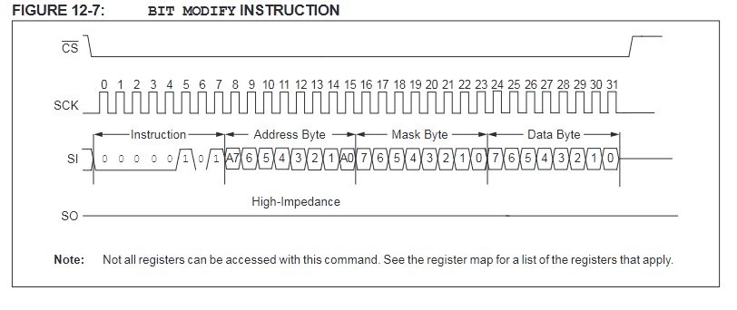
I was tripped up a bit by the STM32 SPI peripheral, which insists on pulsing /CS for every byte when given direct control control. This is so weird. Anyway, the solution is easy enough:

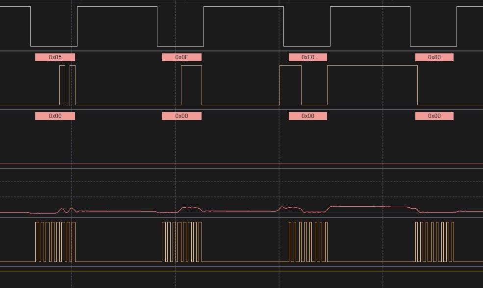
After taking direct control of /CS, the results look much better:
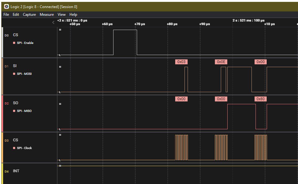
And the CAN messages start to flood in:
main.c:55 main Got CAN message: ID 1374, Length 8, Data: 0x00 0x00 0x00 0x14 0x32 0x00 0x08 0x00
main.c:55 main Got CAN message: ID 407, Length 4, Data: 0x00 0x00 0x00 0x14
With a few minor adjustments to my MCP2515 driver further, I had the ability to send and receive CAN messages. I found some slight issues with the documented protocol (which CRC parameters for certain messages, etc.) and included those changes in my wiki updates, above. With a bit of massaging and cajoling, the gear shifter sprang to life:
Now I have a lovely gear shifter and indicator working on my desk. In gears other than D, it uses an astonishing 0.5A of 12v and gets very warm; this drops to below 0.1A in D. I suppose the motor that prevents you from shifting left and right takes quite some power. I guess back to the battery... for now.
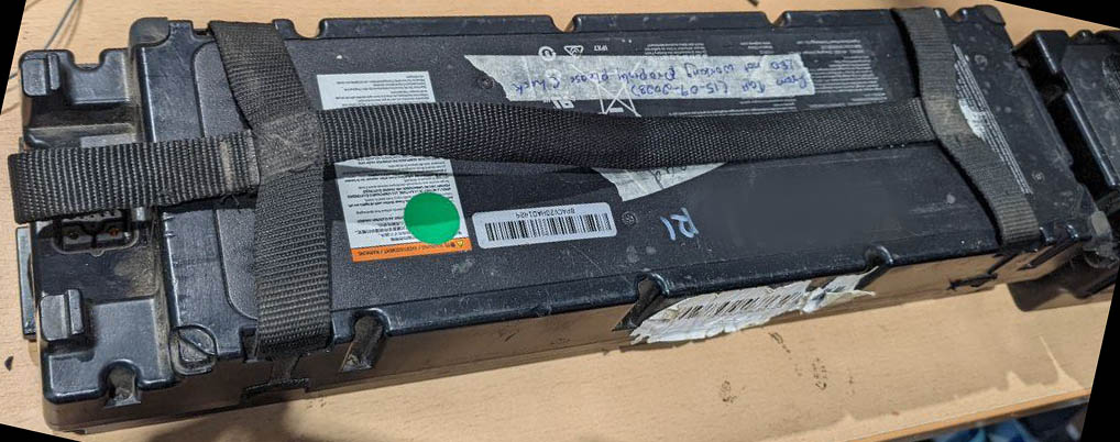
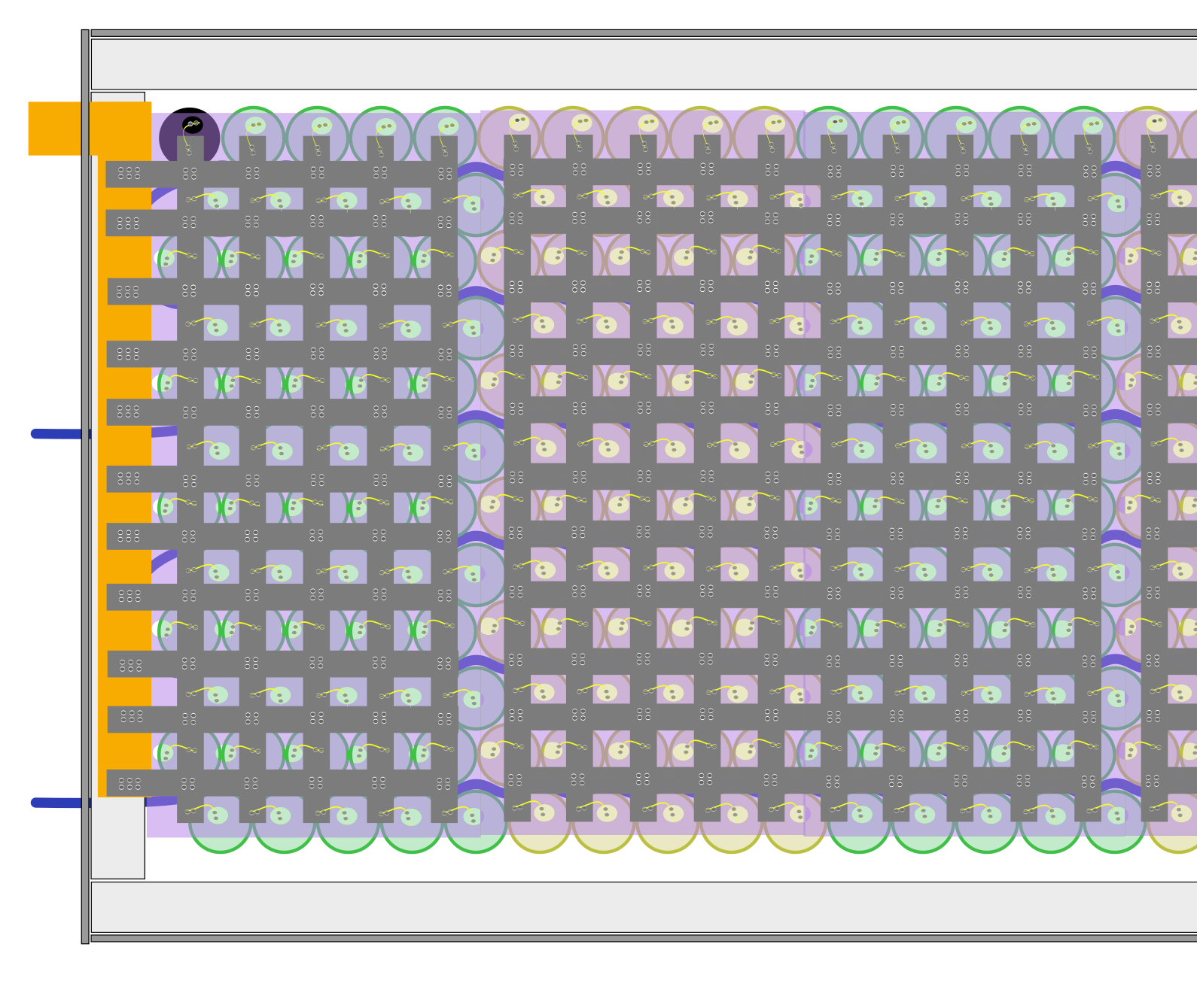
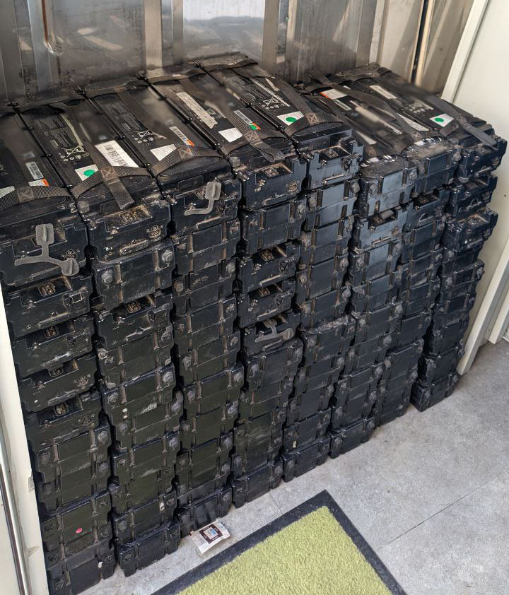
 With the top removed, a first look at the cells and their arrangement, each one neatly encased and connected.
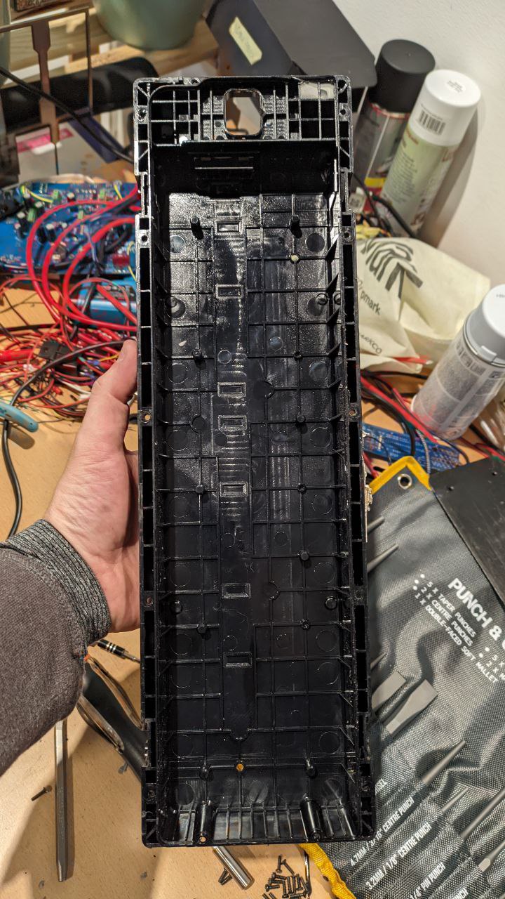 The lone top case.
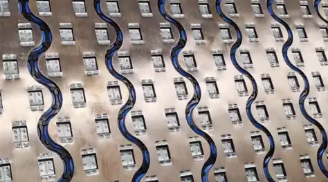
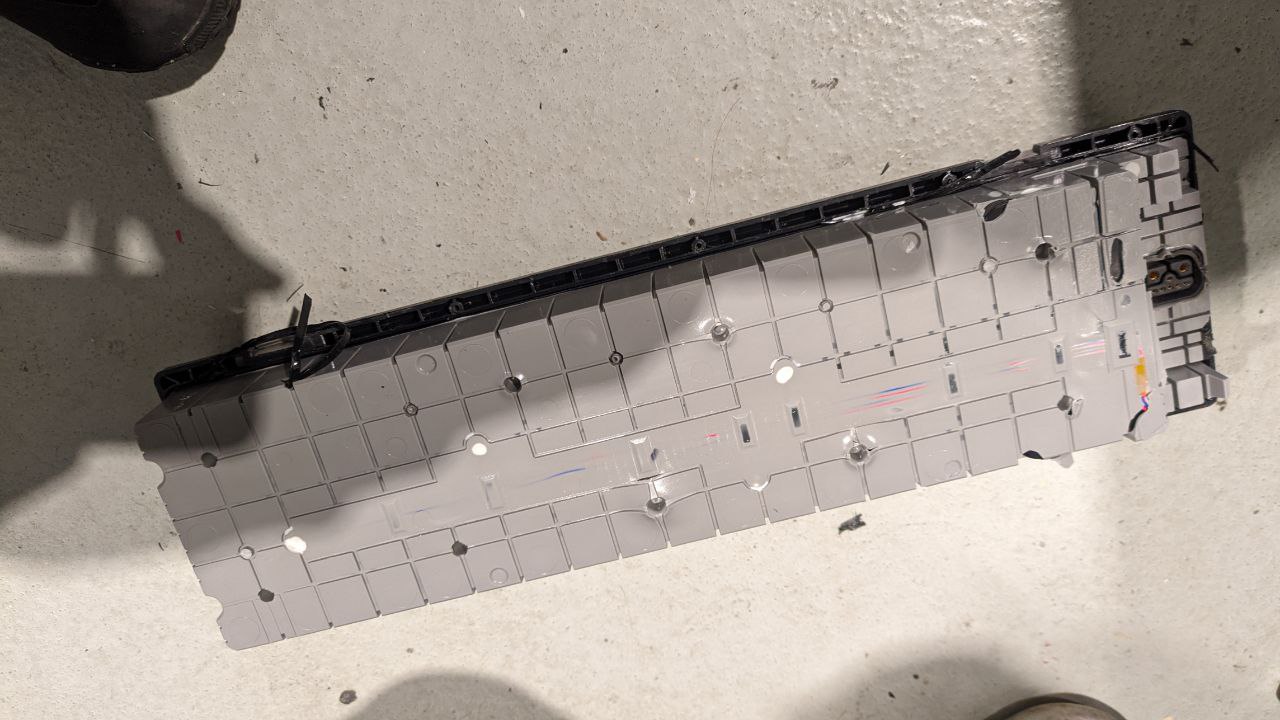
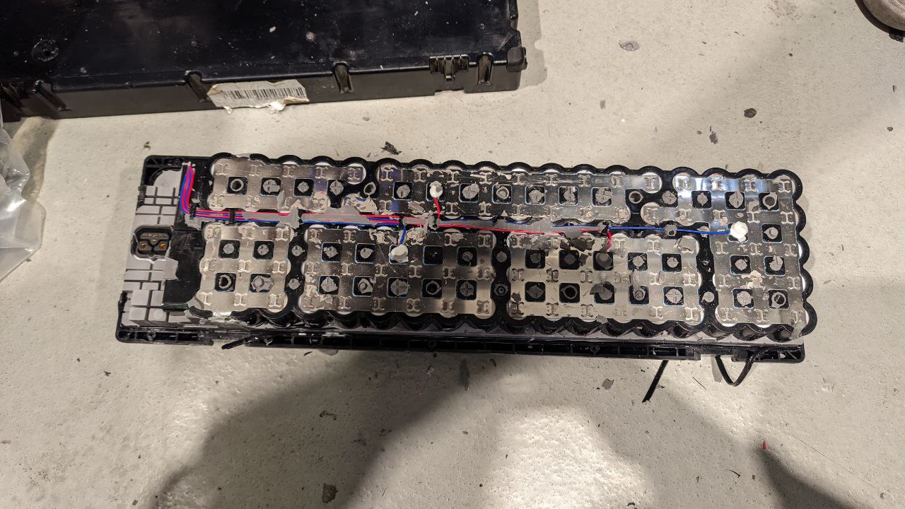 Removing the silicone reveals the electrical architecture of the battery pack.
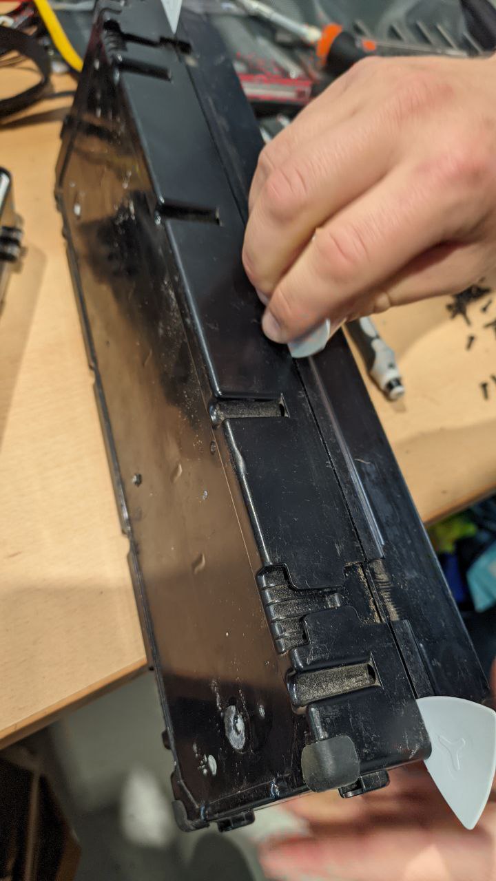
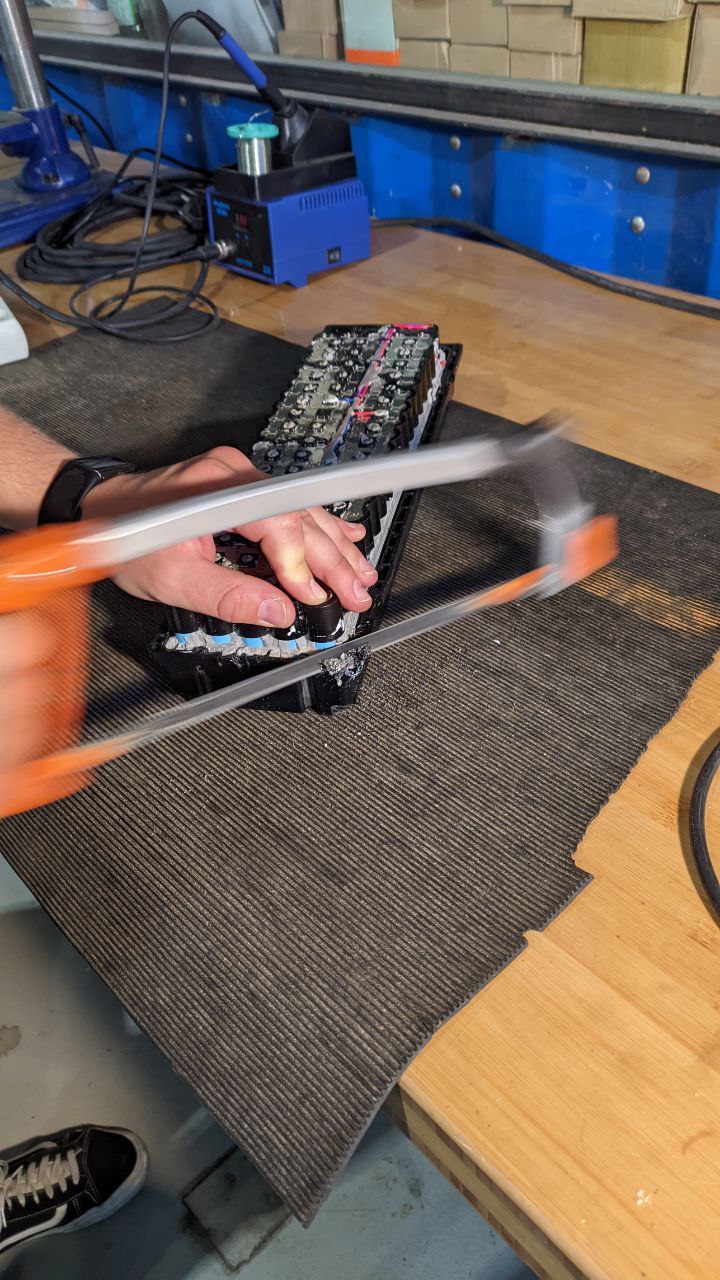 Sometimes you just need a hacksaw...
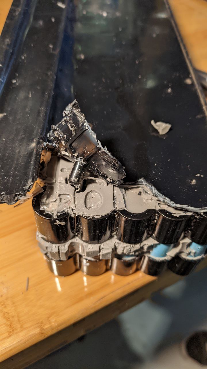 Peeling back the lower plastic
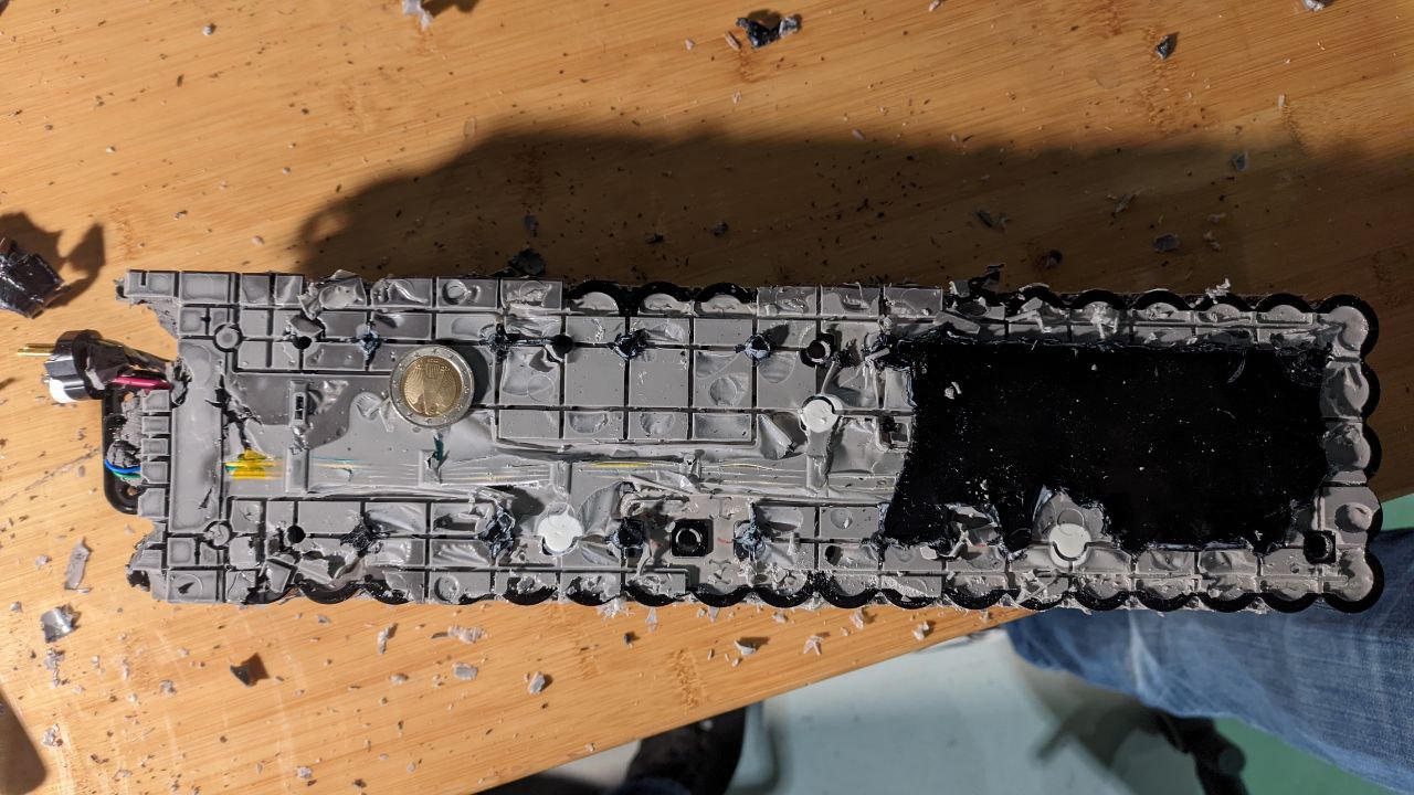 Finally, the battery pack stands bare. We ran out of time, but did manage to verify that all the cells are okay--the groups measured out to 3.7v and the whole pack was still at ~36V